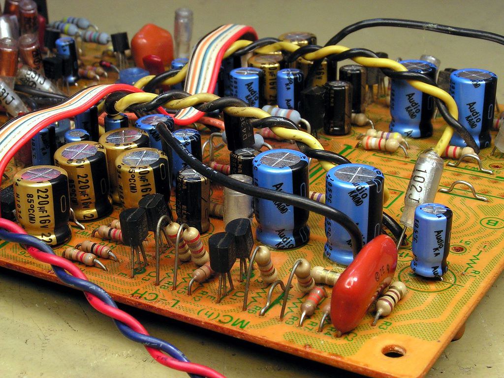
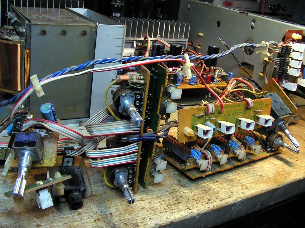
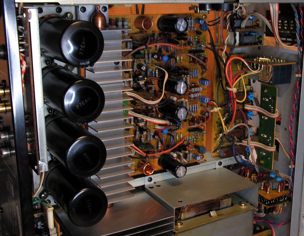
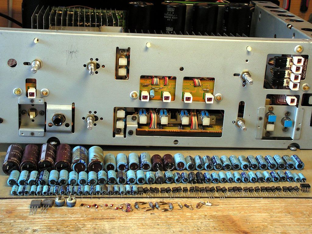
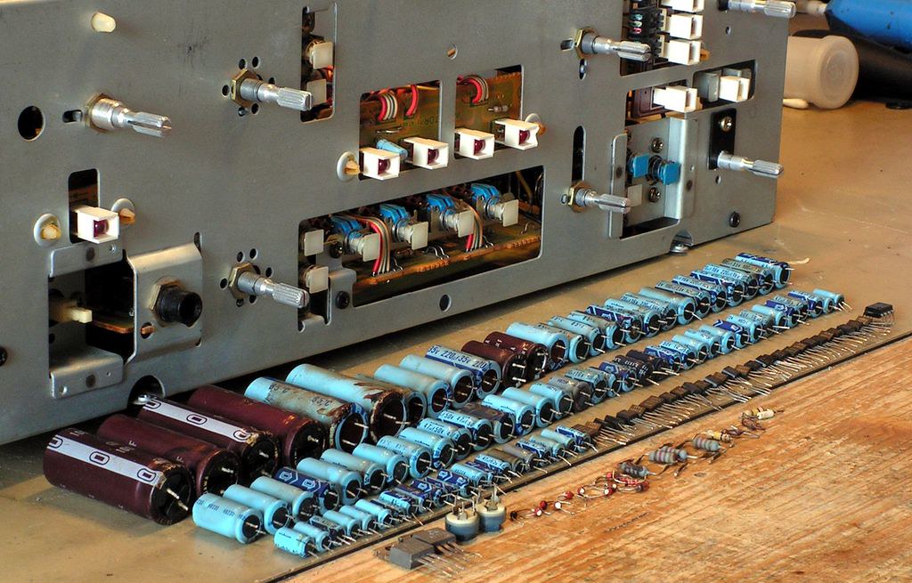
Sansui amplifier, model AU-D9
First, I wish to say sorry what I dont have a picture on which you will see how it was looking when I got it, but I have lot of other interesting picture what I took during my restoration job on that nice amplifier.
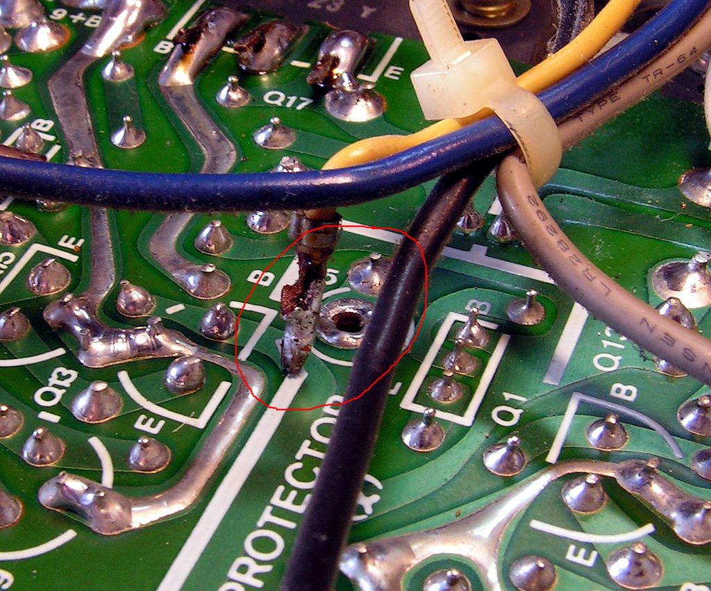
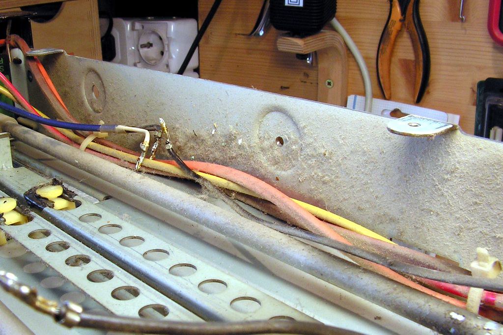
But… right at the beginning this thing was suspicious to me:
This yellow wire was in the air (not connected)!! And uninsulated too!!!
In that moment I knew it will be one interesting restoration….
That yellow wire is one “sensor” for protection circuit, so maybe this amplifier was in protection mode all time, and previous technician fixed this with disconnection of this wire!
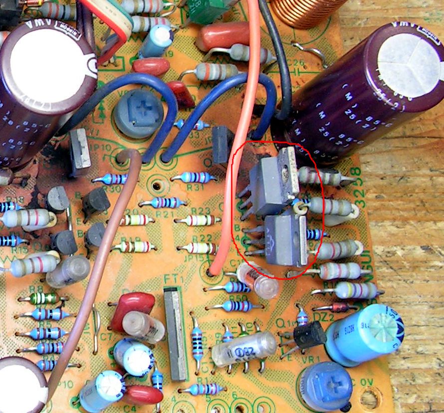
Another interesting thing what I have noticed is this:
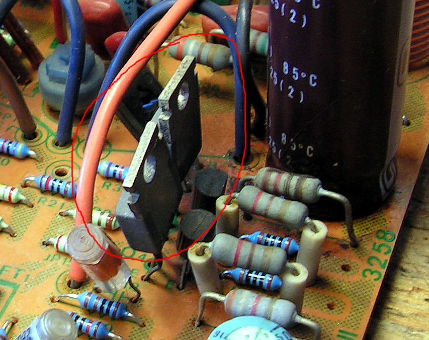
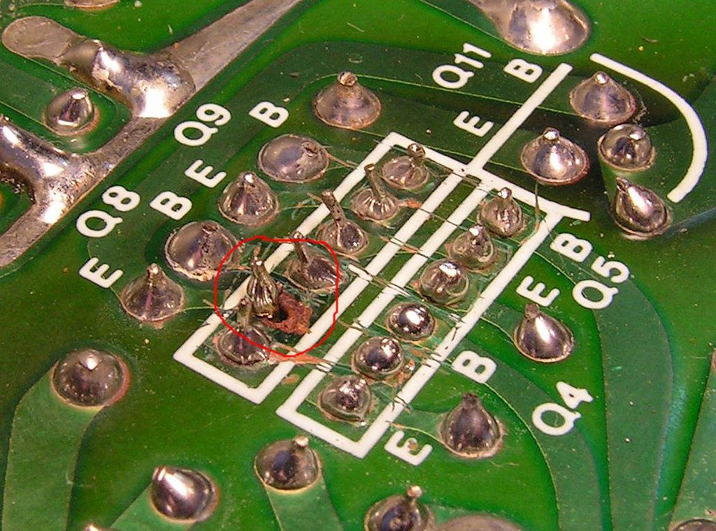
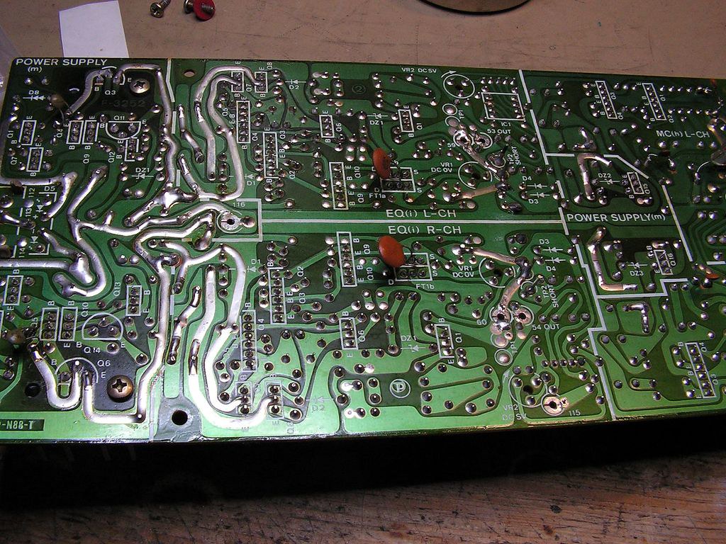
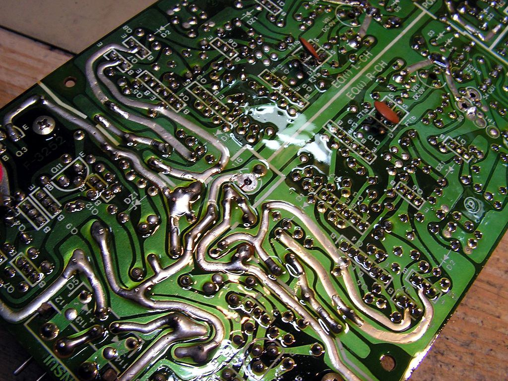
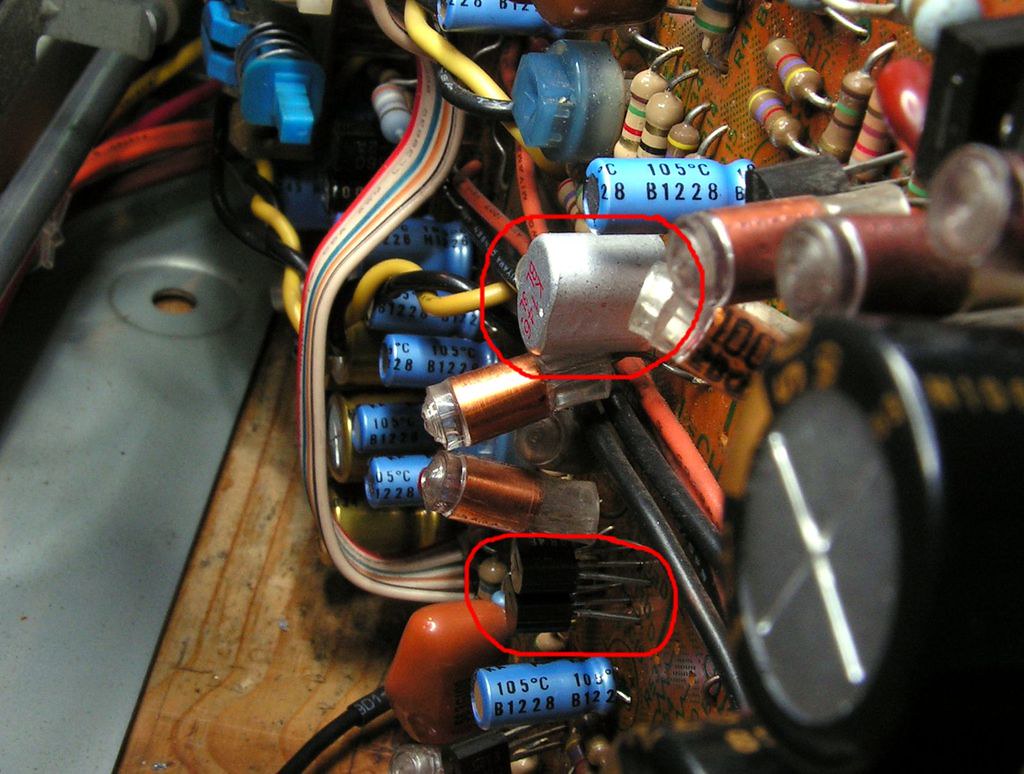
I really dont know why previous technician replaced those two 2sa992 small signal transistors in Diamond-Differential circuit with totally inadequate those TO220 transistors. Because of that you cannot adjust DC Offset to close to zero voltage. I replaced all transistors in complete Diamond-Differential circuit with matched 2SA992 2SC1845 transistors. You see that previous technician changed all carbon film resistors in that circuit with metal film resistors…. it is good but if you asking me, unnecessary.
Plus, the same technician damaged printed circuits during dismounting those transistors…
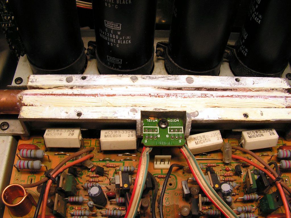
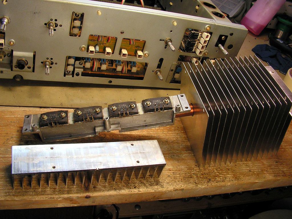
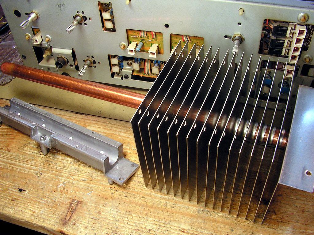
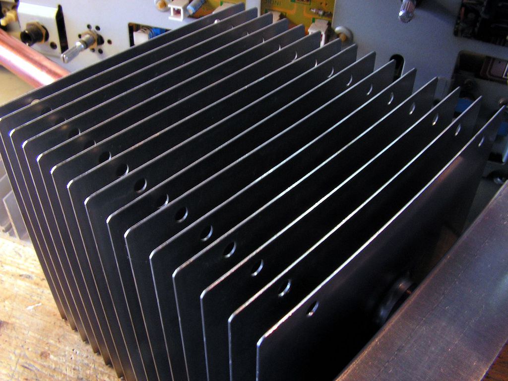
This amplifier has cooling of power stage by heat pipe system. Many peoples don’t like that way of cooling, but it is very effective and it has much less weight as normal aluminum heat sink cooling system. But because peoples like to see a massive aluminum heat sink in theirs amplifiers, and because heavy weight amplifier is more audiophile than less weight amplifier, Sansui quit in later amplifiers with that way of cooling and they came back to aluminum heat sink…
I removed entire old thermal grease and putted a new, washed all parts of that cooling system…
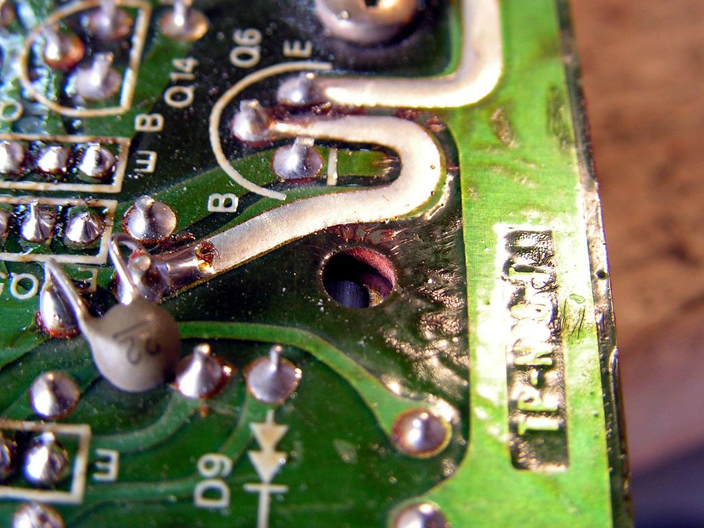
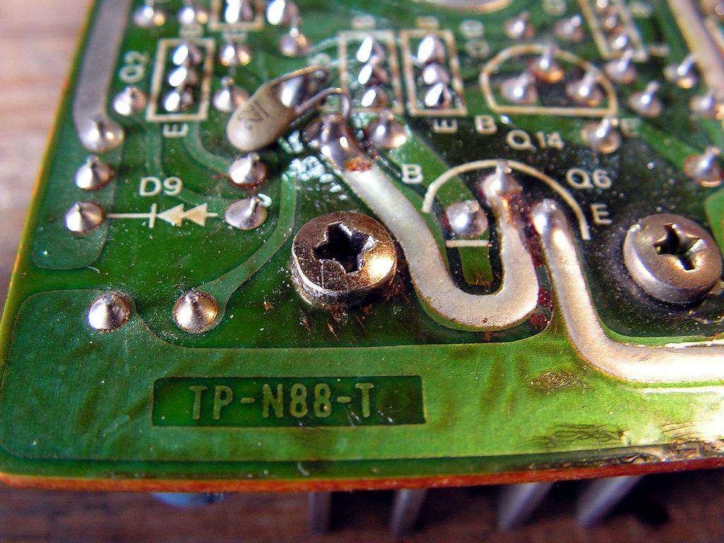
… but, please look those holes:
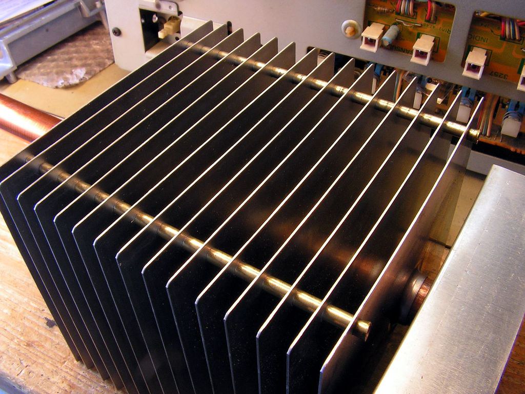
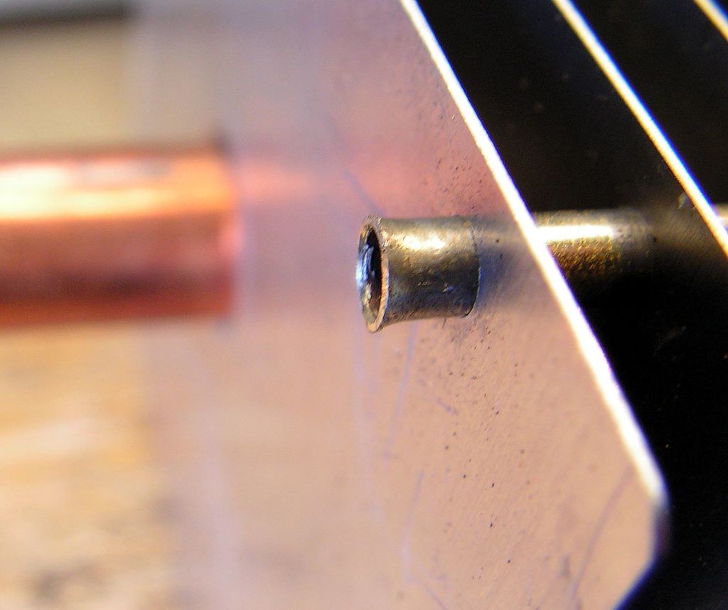
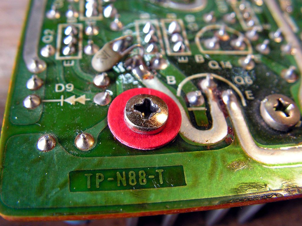
Those holes were for fixing parts of that heat radiator, I dodnt know why Sansui didnt fixed them… so I did that job on this way:
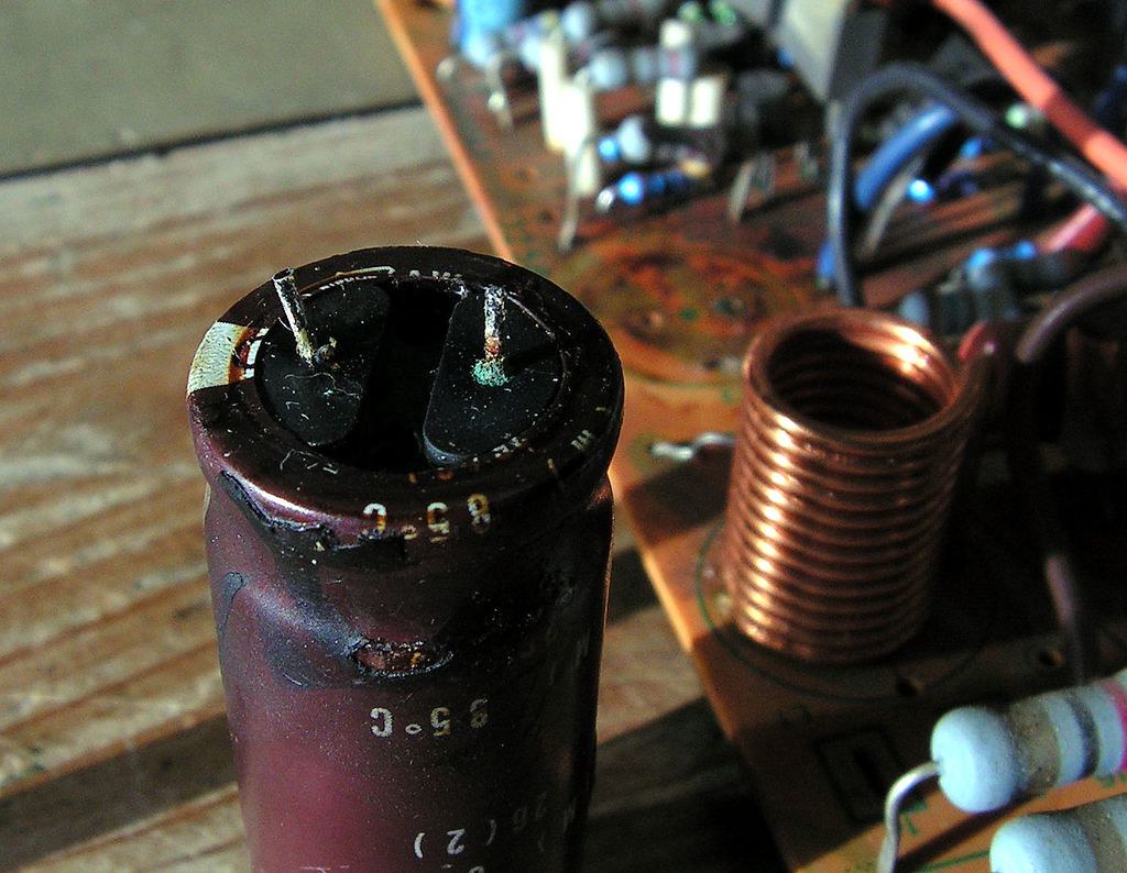
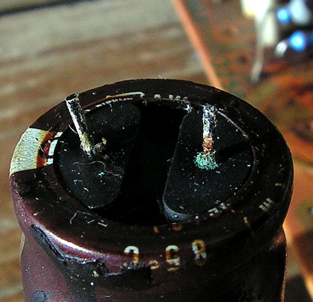
On the next picture you can see how it look like connection pin of one capacitor what was on the driver board…
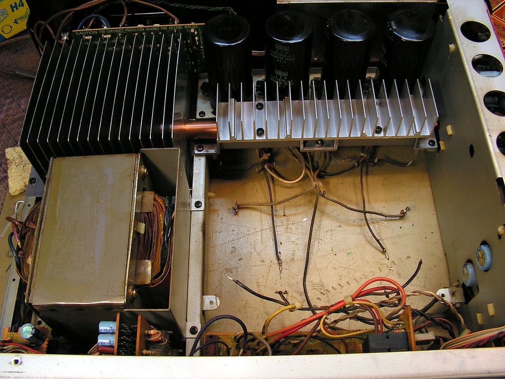
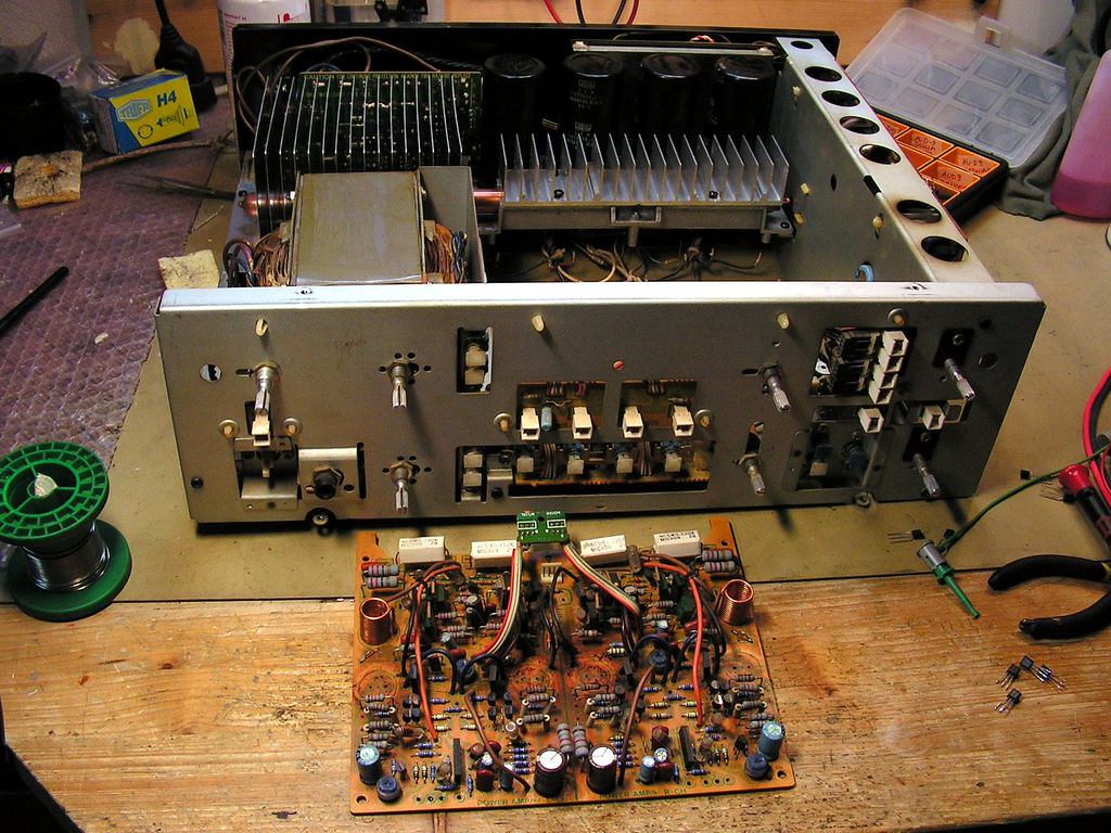
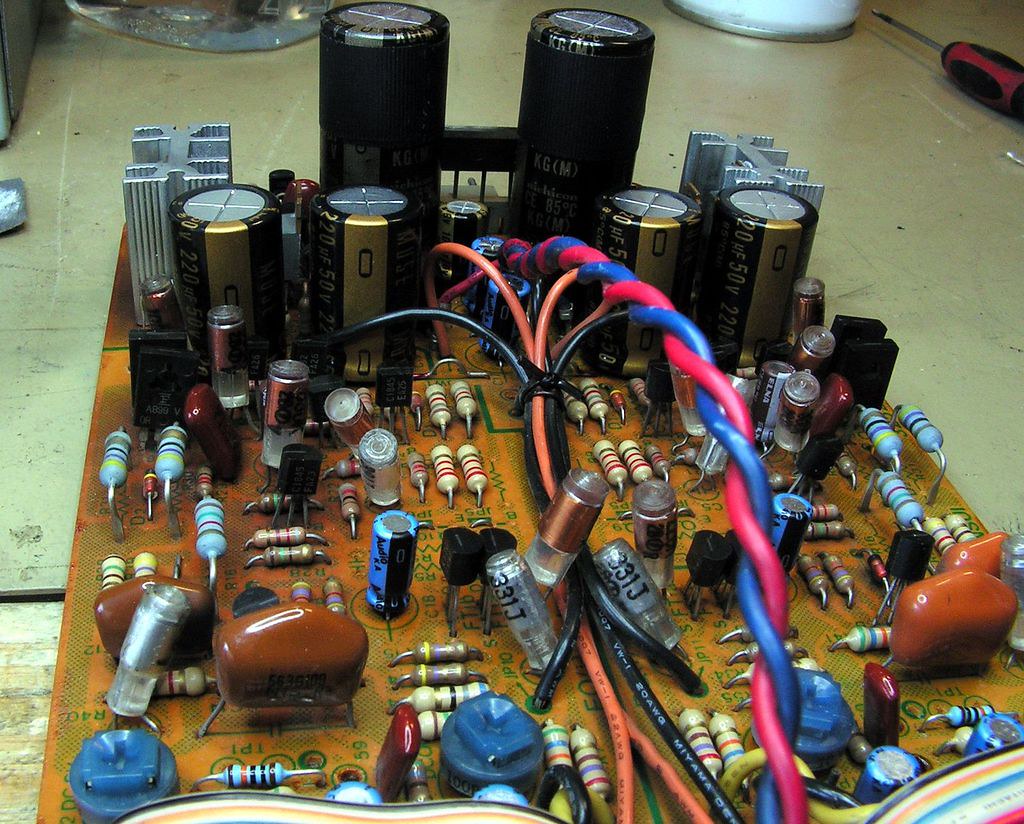
And here it is amplifier without Driver board
The next step was Phono / Power Supply Board… after I disassembled the board, I noticed that the space below board was not so clean…
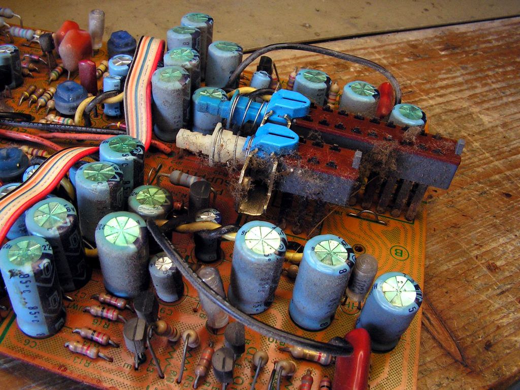
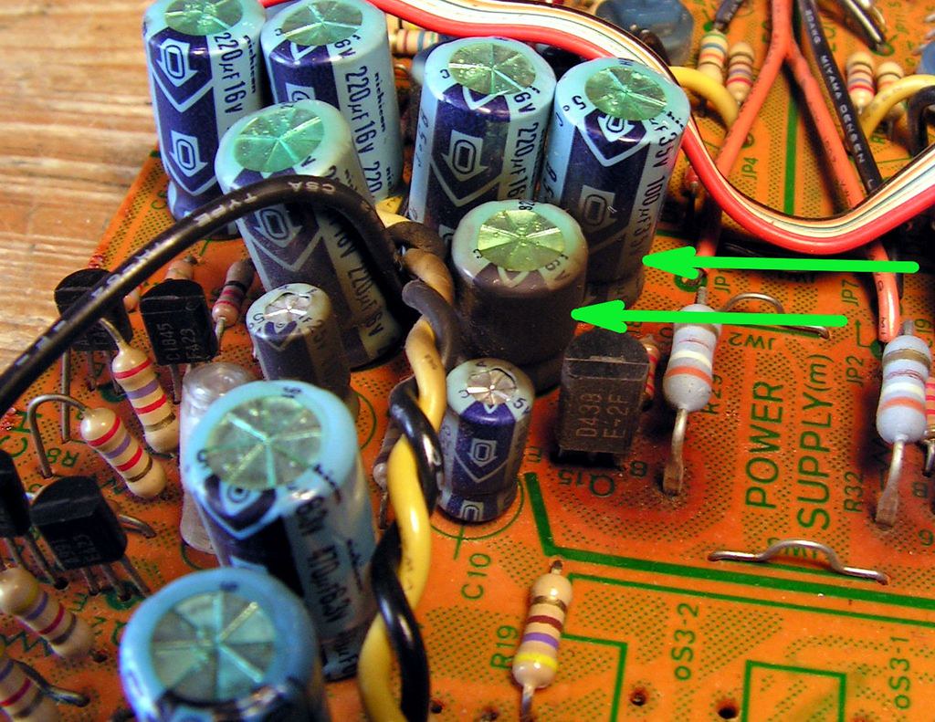
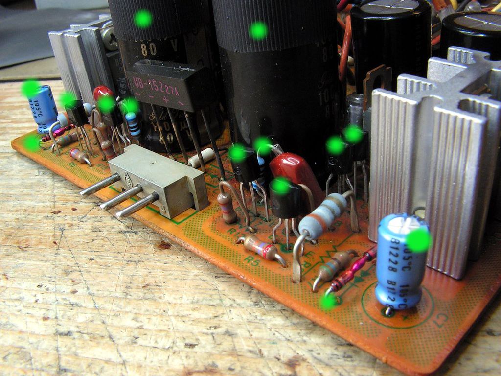
The next thing what I have noticed is that on some parts of this board generated so much heat, look
That is not some shadow!
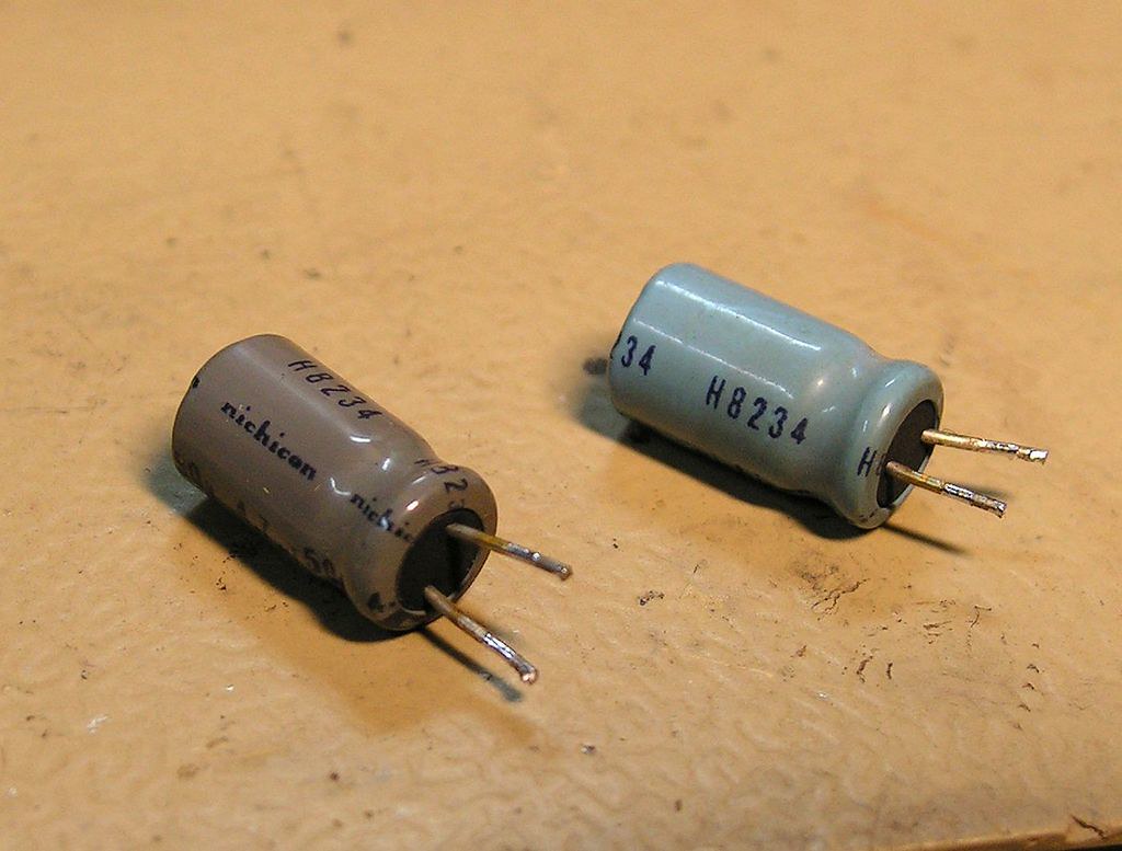
And on the next picture you can se two the same capacitors what I have removed, first was close to heat element, and the second was not…
That is known Sansui glue what is completely darkened because of high temperatures.
Because of all I decided here to use Nichicon KA series of audio capacitors which are 105 degrees C
Ok,let's continue…
Here I made one upgrade 🙂
This is a situation what I have found
That hole was for another screw which fixing TO220 aluminum heat sink to the board.
I was wondering how Sansui forgot to put that screw, but when I did, it was clear to me why Sansui didn’t put that screw at that place… it is so close to the printed circuits!
And solution for that is:
Simple and efficient!
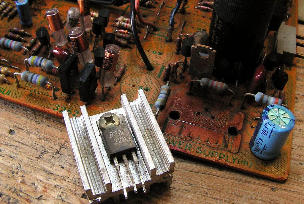
This is aluminum TO220 heat sink about what I was talking in previous post…
But I must say that I was very surprised how in badly condition was thermal grease between that transistor and heat-sink! That was not grease any more, that was some kind of dried mixture which I could not remove, not even by thinner!
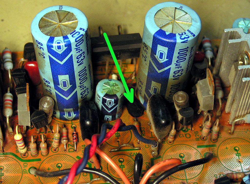
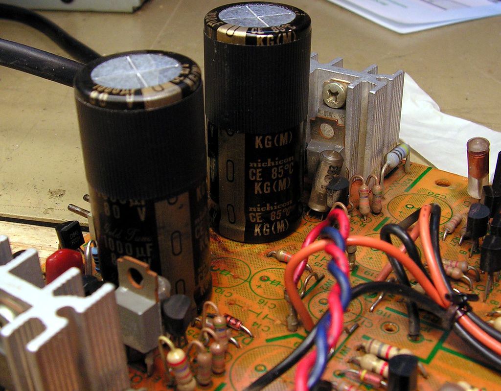
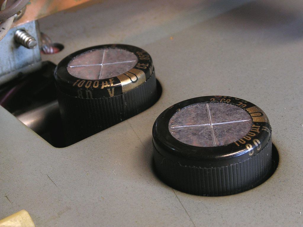
And I did a big job to instal those two 1000uF Snap-In capacitors instead old normal radial capacitors…
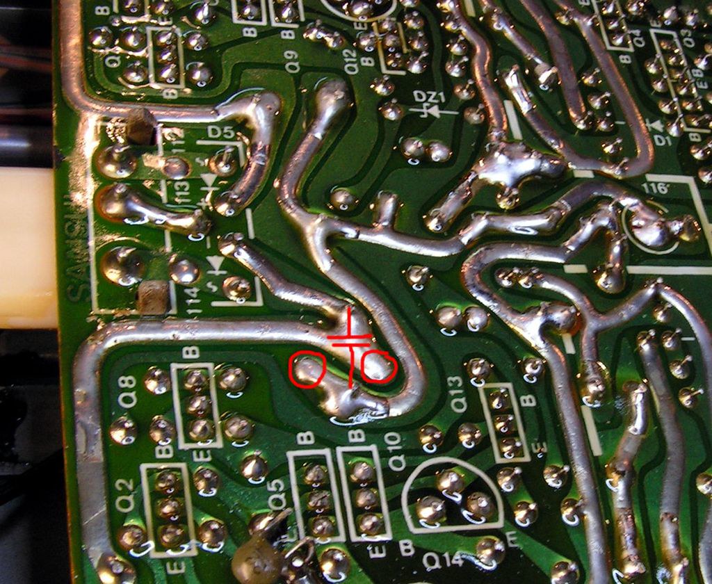
I had to made a new contact points on circuit board for that capacitor because it had bigger raster than old ones… capacitor symbol show how it is connected now, and circles how it was before…
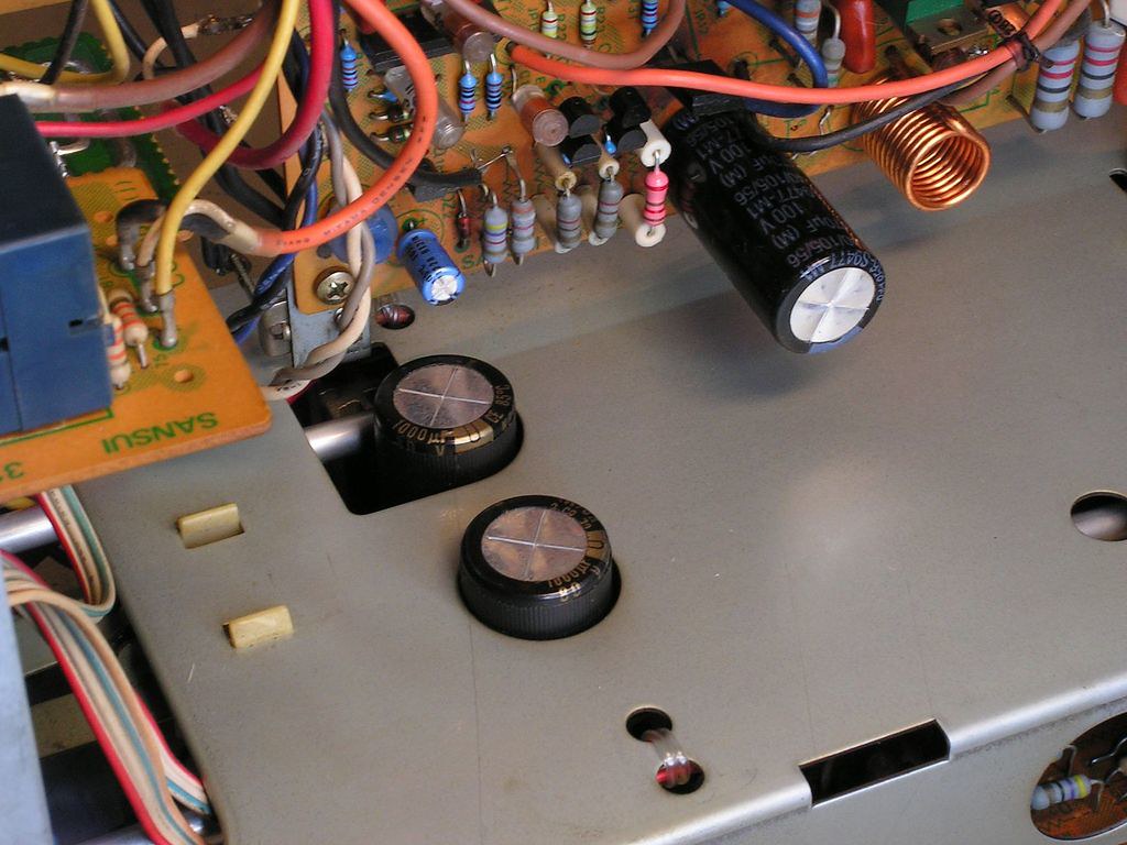
… you should be very careful where you will mount those capacitors, because they are not so small, and look where they will be after you install back that board into aplifier…
… and what has changed just at that part of Phono Board…
And another board is ready for installing….
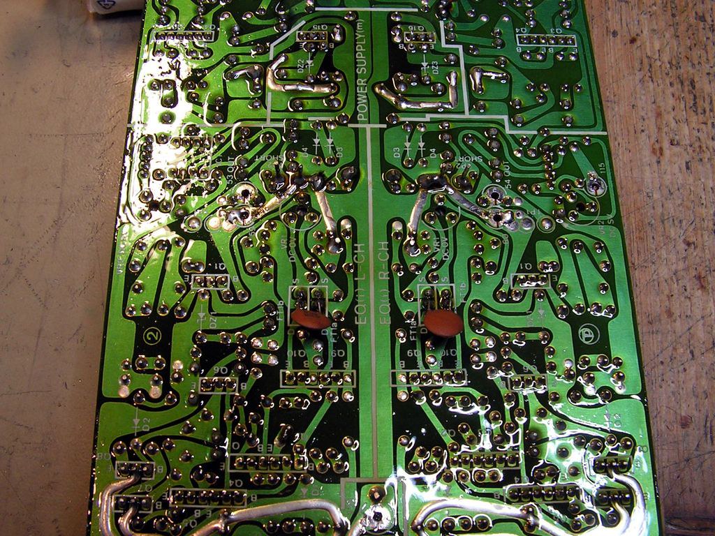
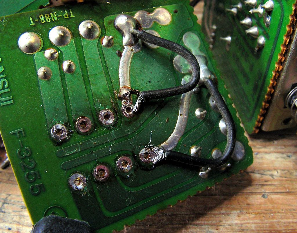
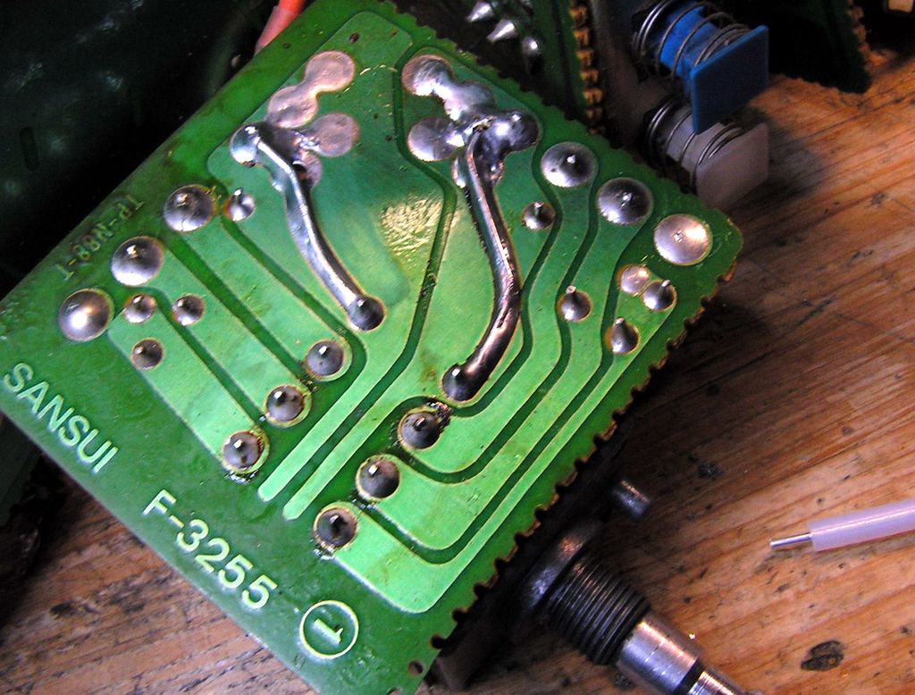
On that picture how it was looking after I removed complete old rosin
and how it is looking now
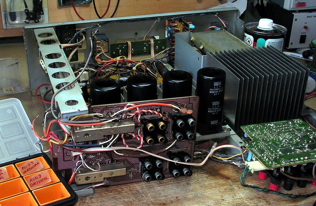
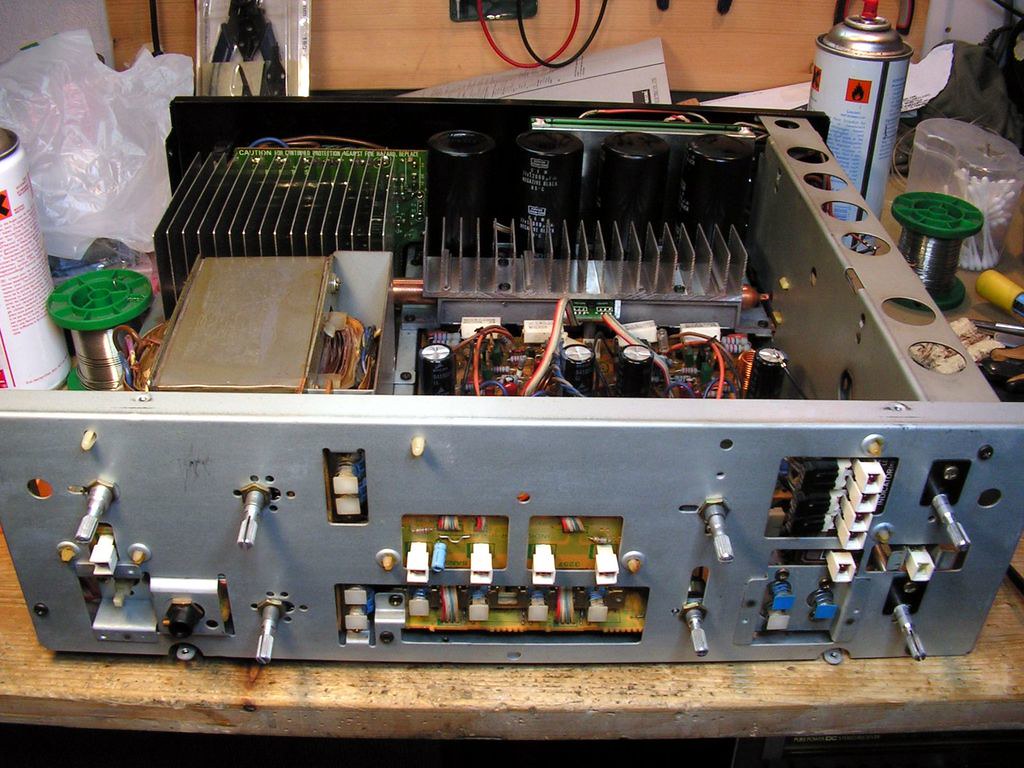
And now we are moving to the back of amplifier…
And here I had one very specific problem…
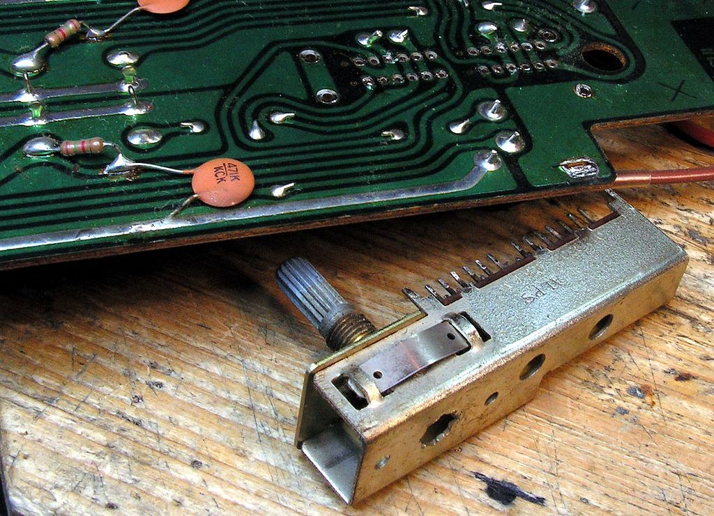
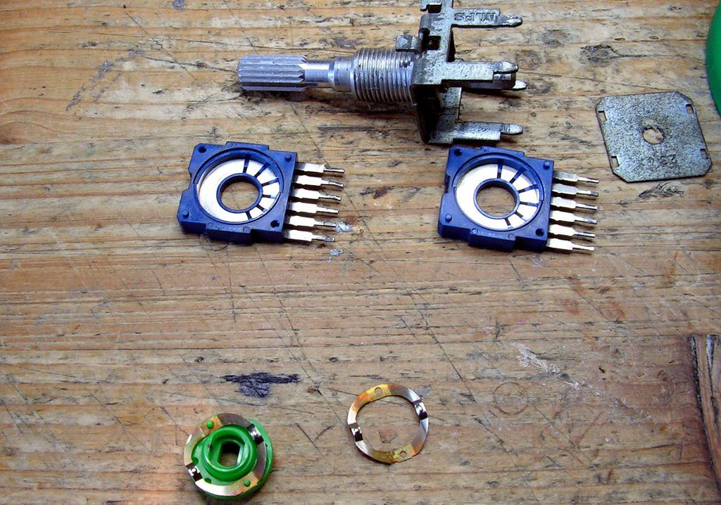
When I desoldered all pins of that selector from board,
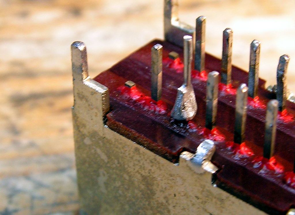
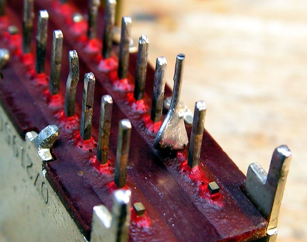
some of them was bent (that was done in the factory to fix selector to the board before soldering complete board)… and when I tried to straighten it, it was broken! So only what I had to do is to fix it on that way:
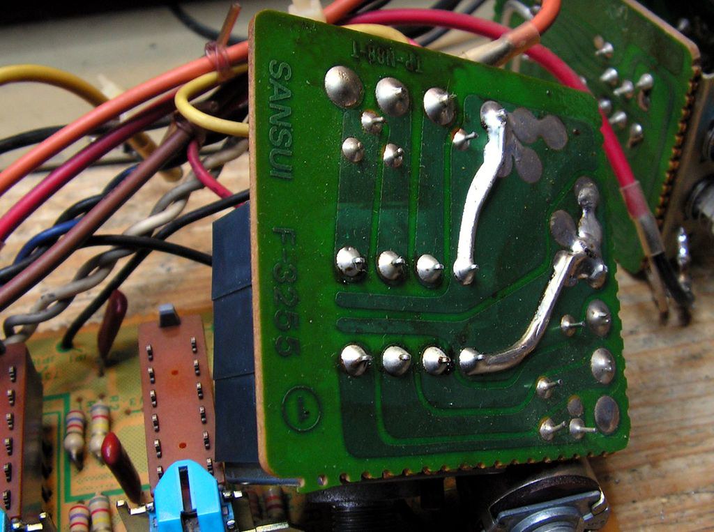
Continue … classics … cleaning
… how it was….
… how it is now ….
… another selector…
… cleaned …
Here I would like to stop, just to show you one very important detail detail…
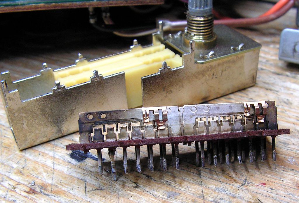
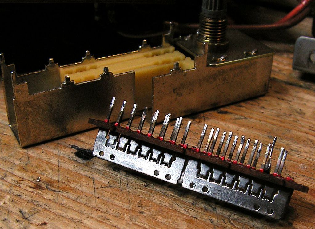
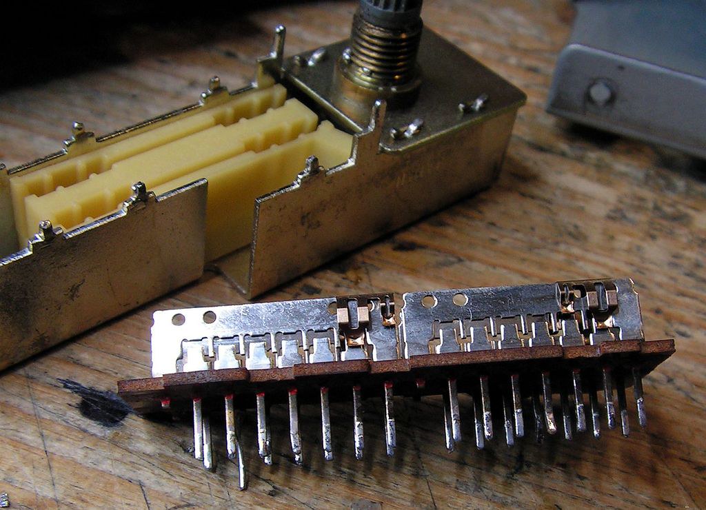
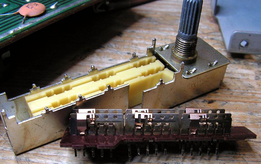
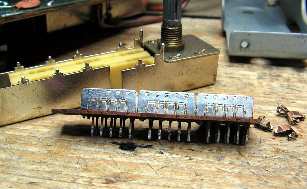
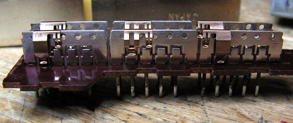
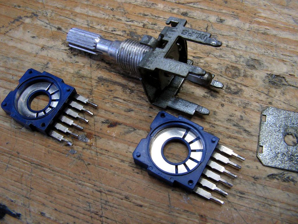
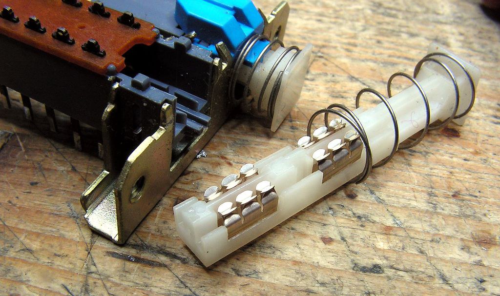
Look at the contacts of that selector:
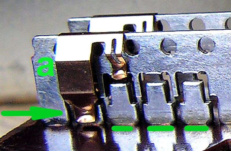
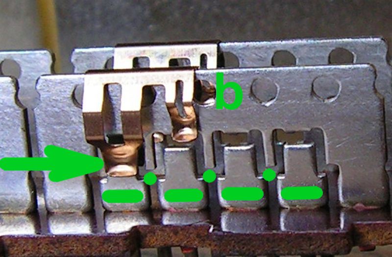
as you probably see, there are two types of contacts, two are longer (type "a") and one is shorter (type "b")
First contact type "a"
When it is moving from position to position, at one moment that contact connect common contact with two slave contacts.
and now contact type "b"
when it is moving from position to position, Common contact never make contact to the two slave contacts in the same time!
Why I am telling this? Because you should always be focused on the task, and you should pay attention to every detail during the restoration job…
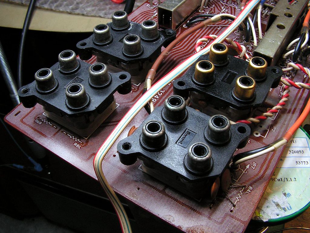
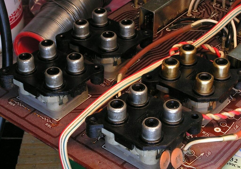
Those RCA connectors was not looking so nice, so I decided to polish them
and now they looking very nice….
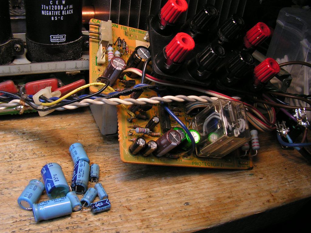
…replaced all capacitors at Protection Board…
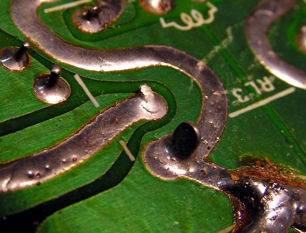
… some solder points on that board was not so good….
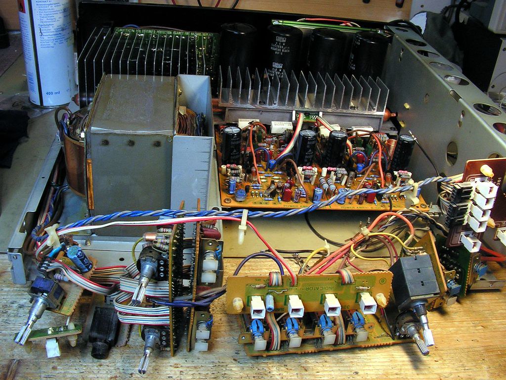
And now… we are moving to the front side of amplifier…
… speakers selector …
… and wait… I must show you something here!
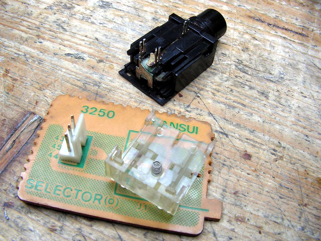
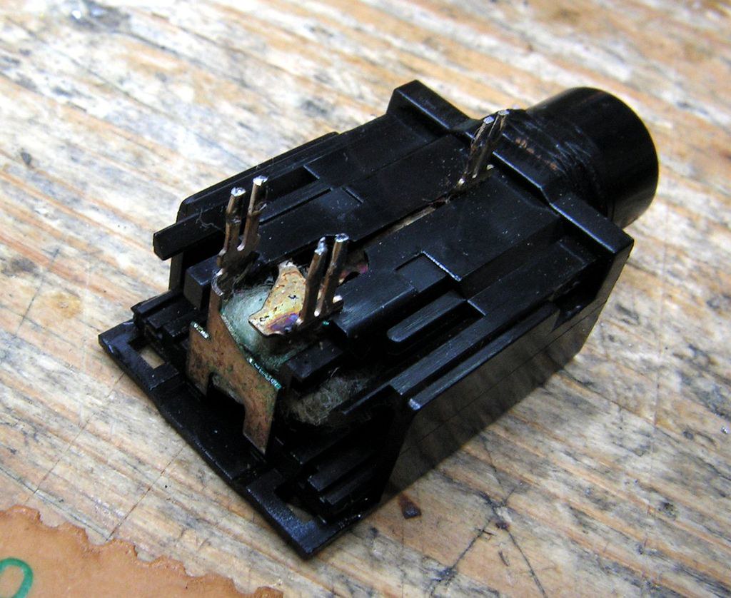
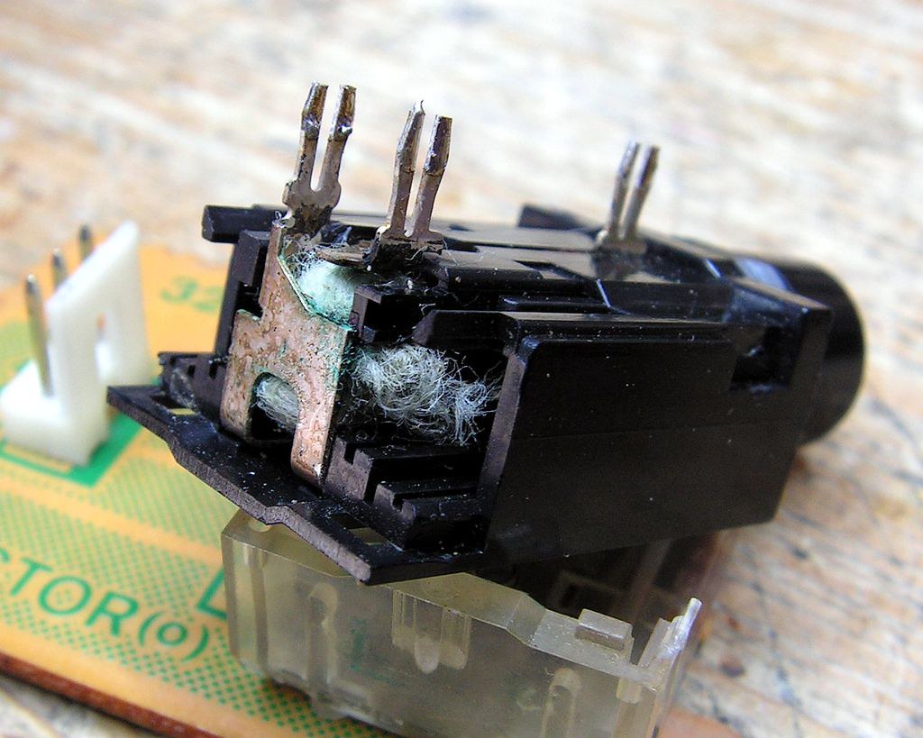
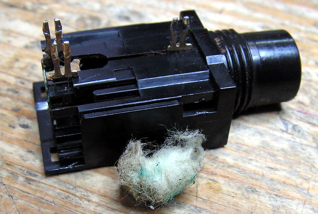
That what you see on that picture above and below is PHONES socket, but do you see something strange???
You dont!?!? OK… do you see now?
Hahahaha 🙂 please look what I have found in that PHONES socket
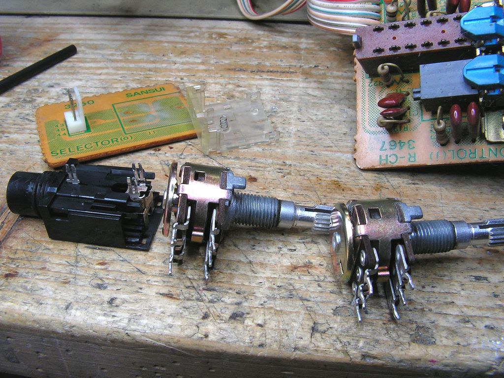
… and those parts are clean now and ready to instal…
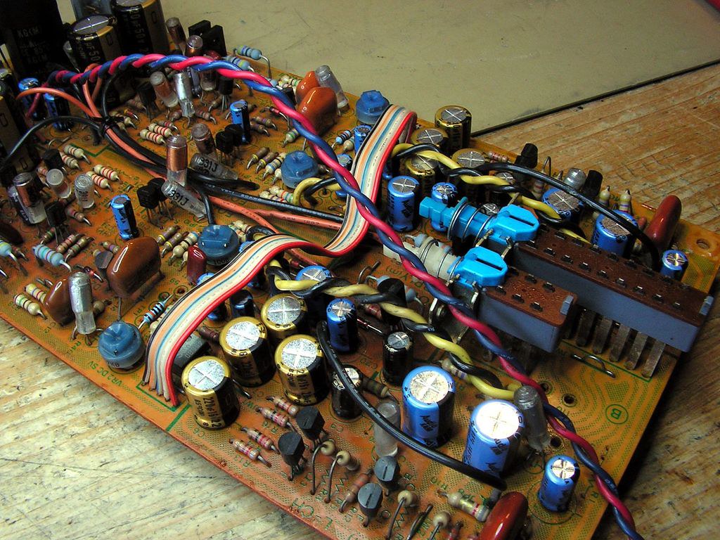
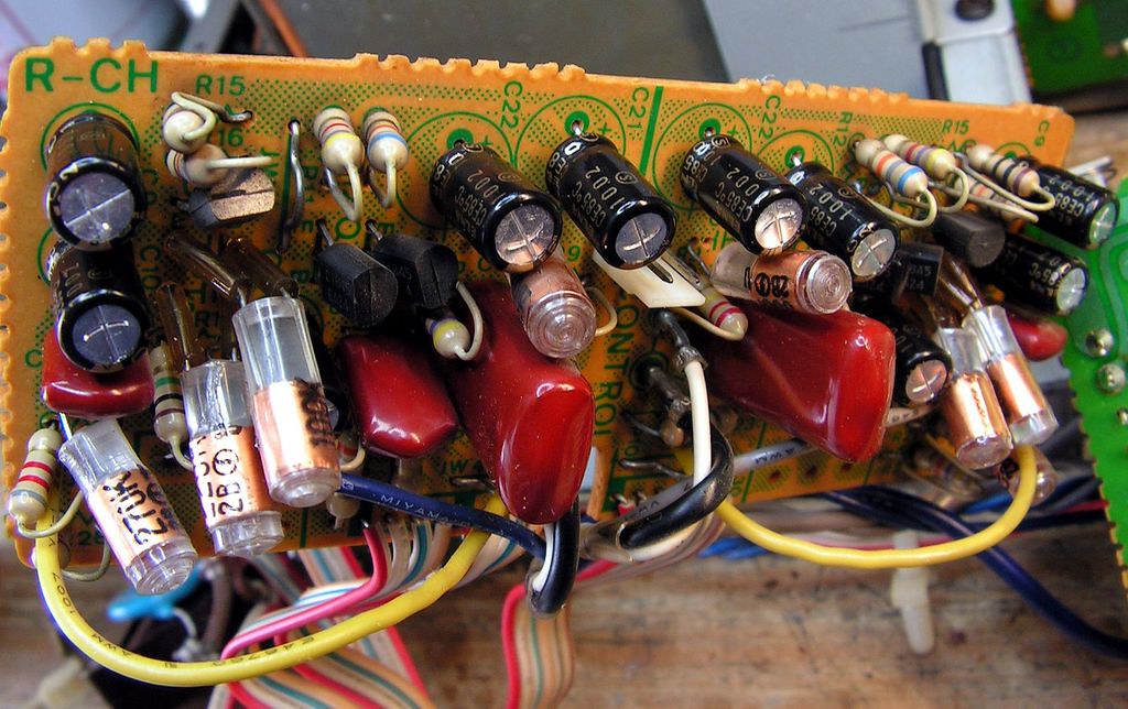
On the Tone Control board I replaced old capacitors by ELNA Cerafine capacitors
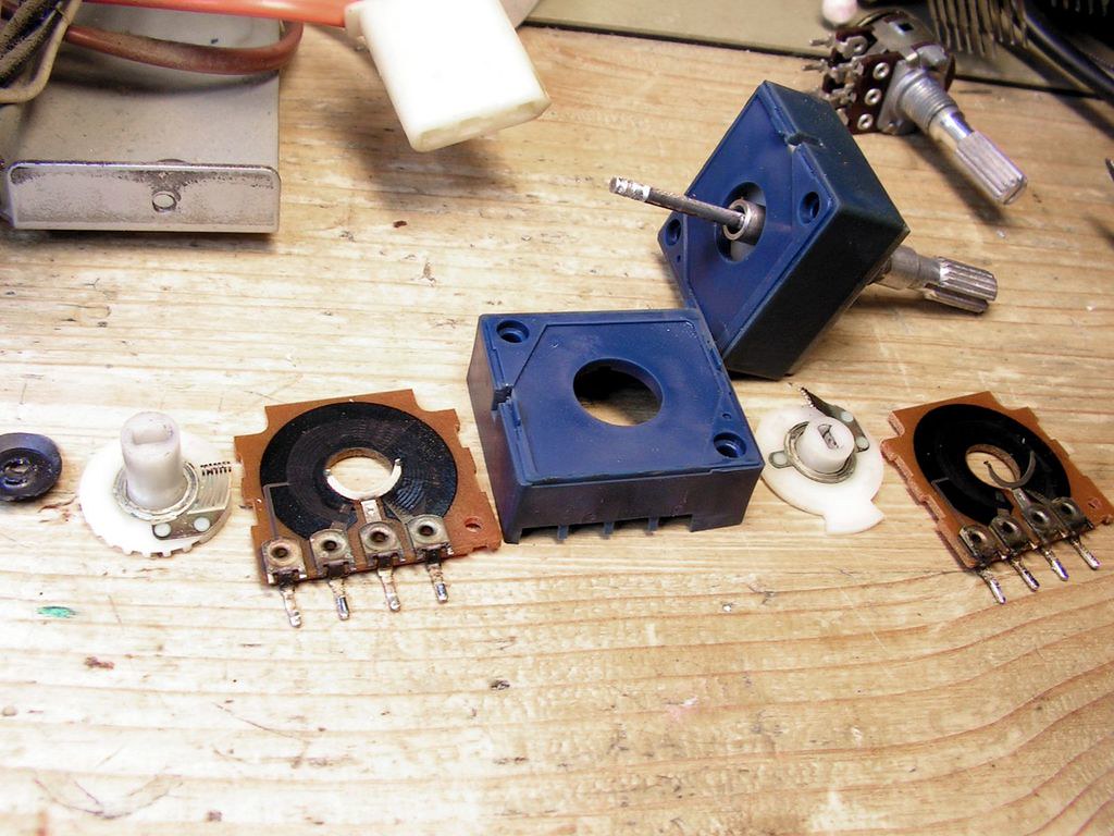
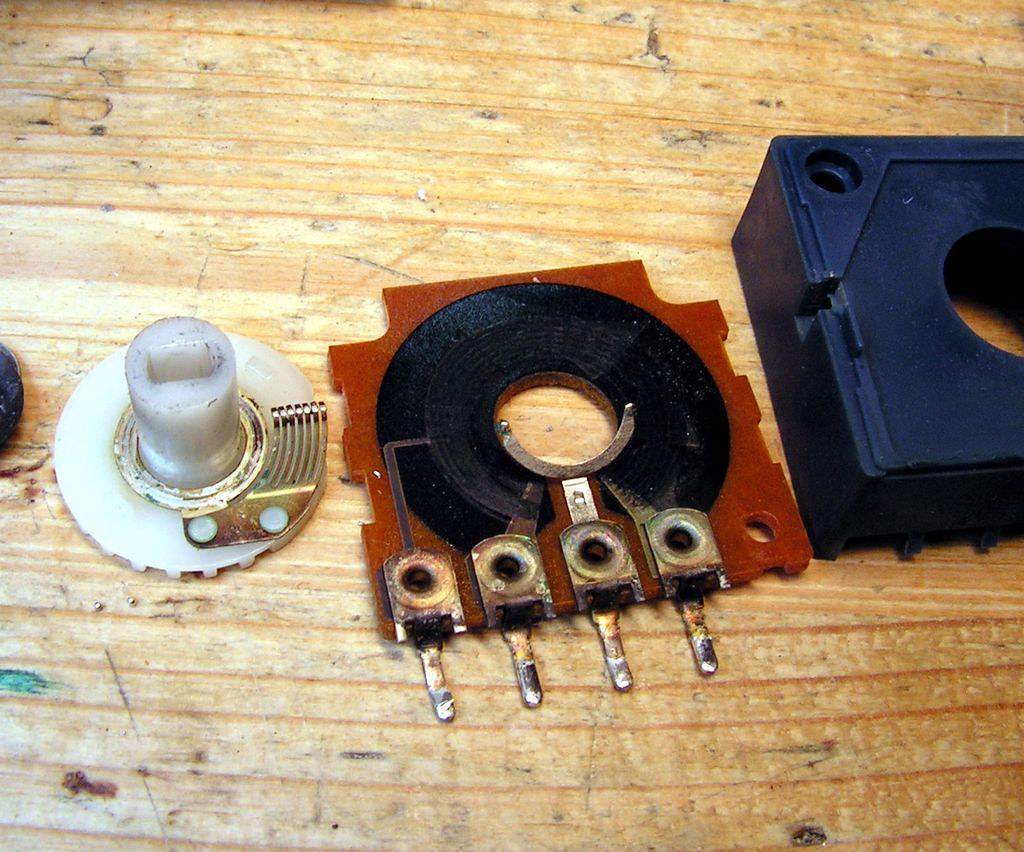
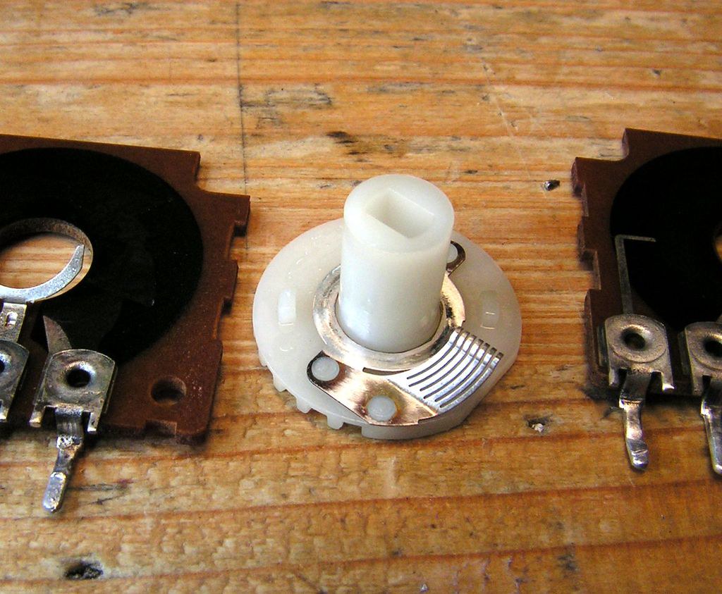
But I was very surprised when I saw disassembled switch for tone control and contacts inside of that switch
They were in very god condition, without oxidation!
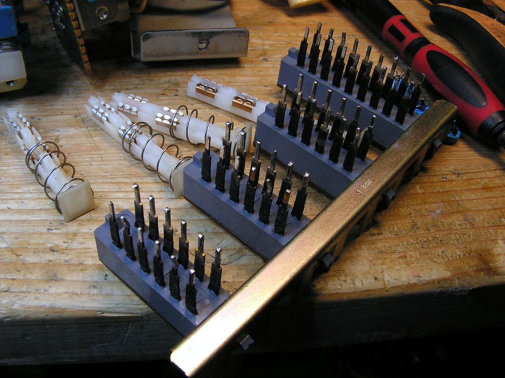
OK, when I already disassembled them, I did one simple cleaning job…
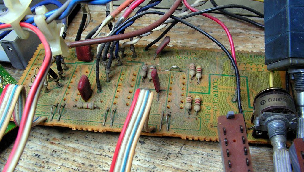
But board where those switches was placed, was not so clean….
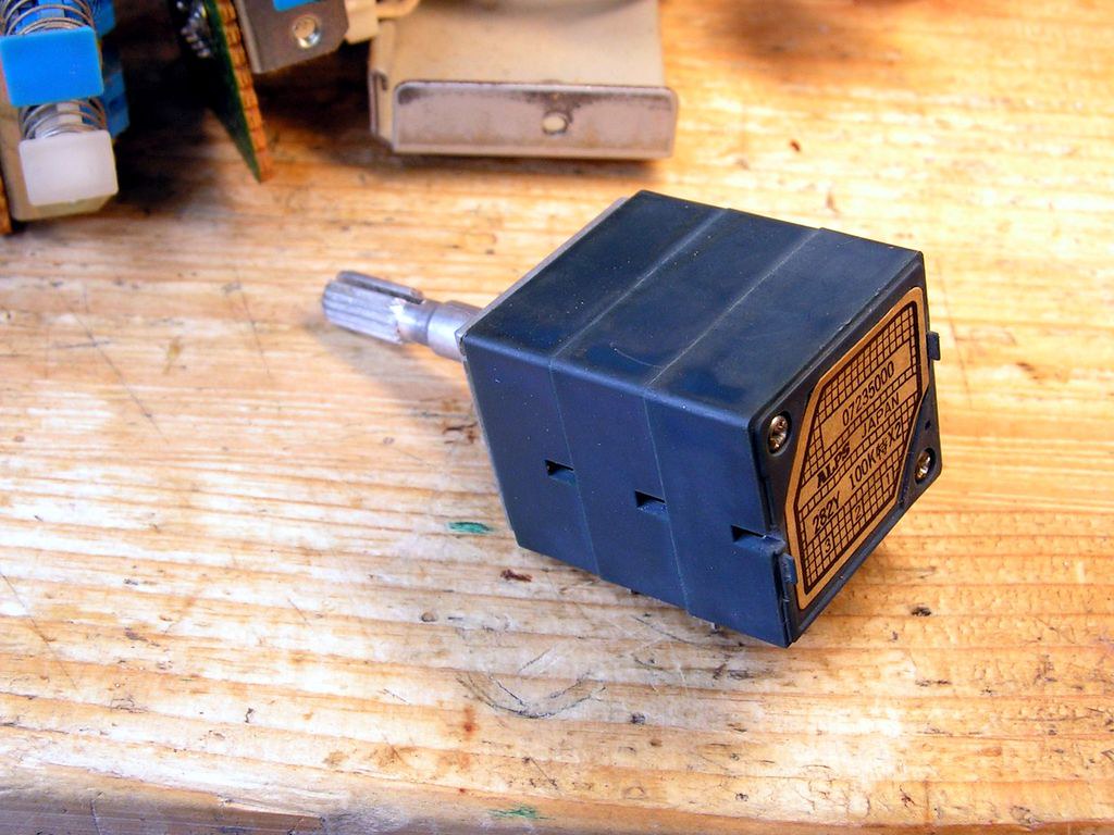
… Blue Alps volume pot….
… and cleaned…
… ready to instal …
I made a small change at volume pot board:
Those black ground wires are not so nice to see, so I made the same thing but on some different way…
and afterr all… FINALLY!!!!
And first power up…. uf… the white smoke remained inside of the device 🙂
… or clearly said … amplifier works as it should.
But during adjustment of phono preamp board I could not to adjust DC Servo to close to zero volts! No way!
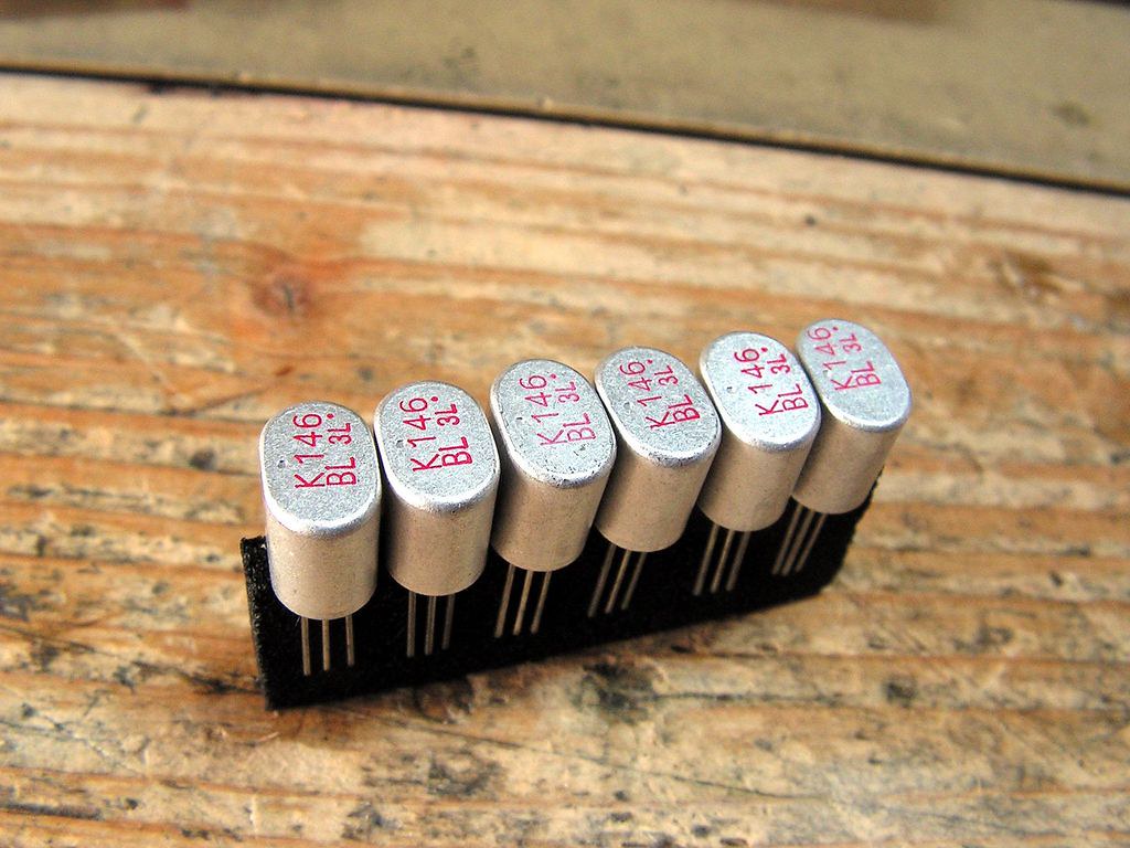
And I have found why… previous technician changed 2SK146 dual diff. fet by two, not matched 2SK117!!!
It was good what I have some of NOS 2SK146 on my stock…
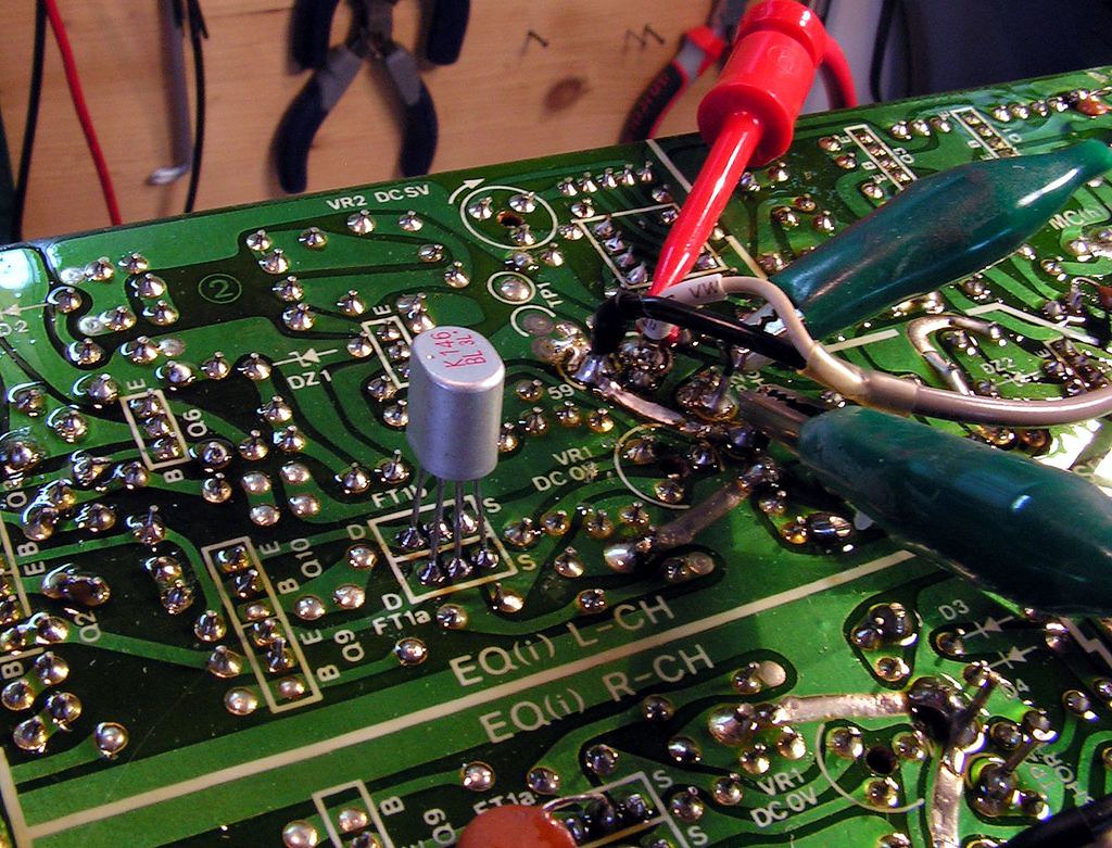
But this time I wish to be sure, I temporarily soldered that 2SK146 on printed circuit side of Phono Board, and… yes… now it is all OK…
On the next picture you can see a new 2sk146 and below it, those not matched 2sk117
And we are close to end…
What was changed during this restoration:
And now some pictures about testing amplifier….
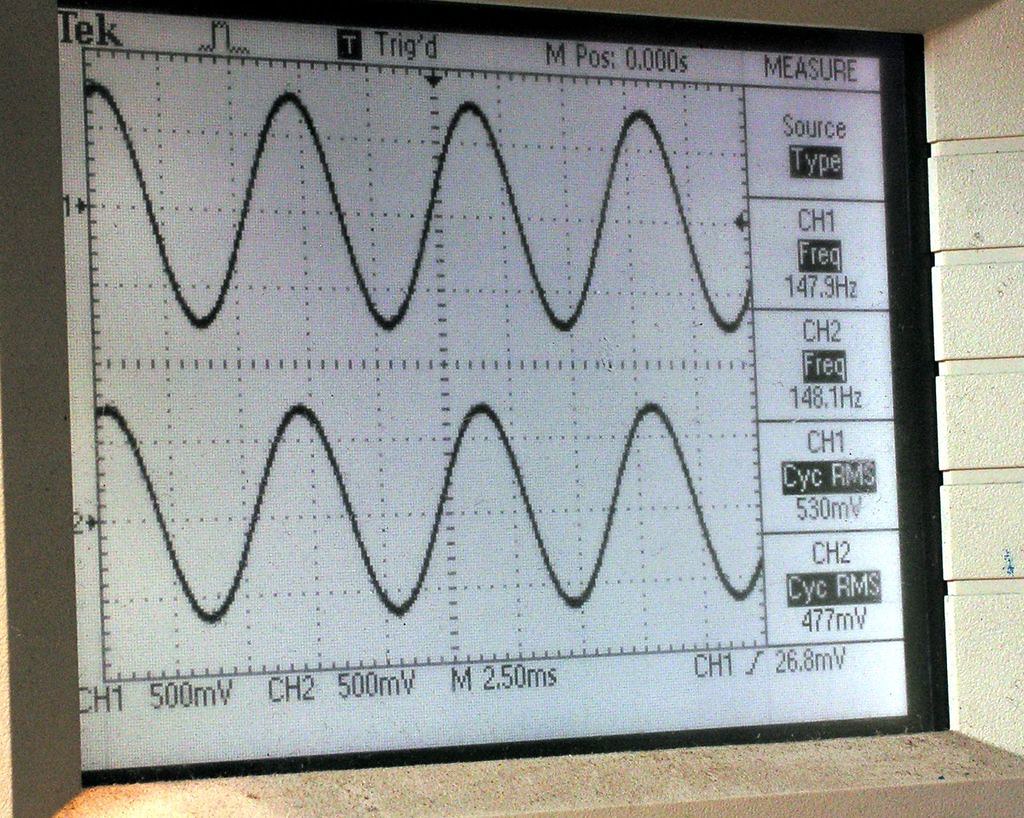
First Phono input → sinus 150Hz → taken from speakers connectors
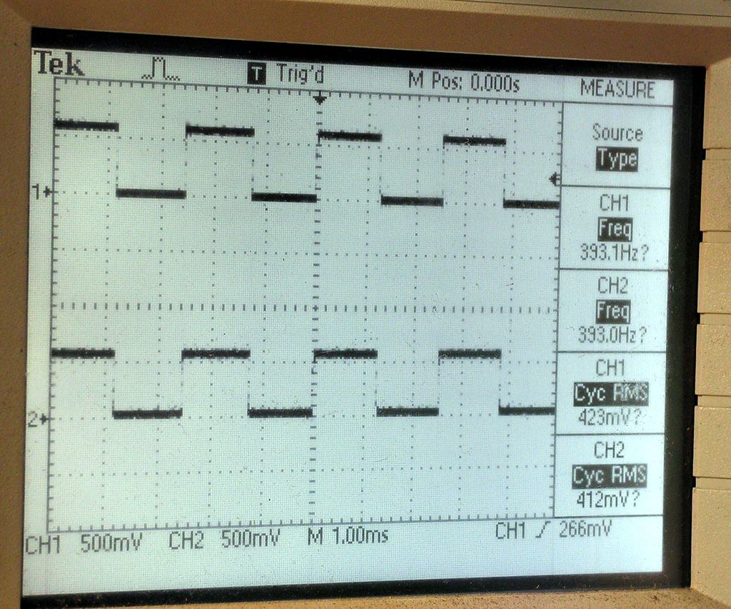
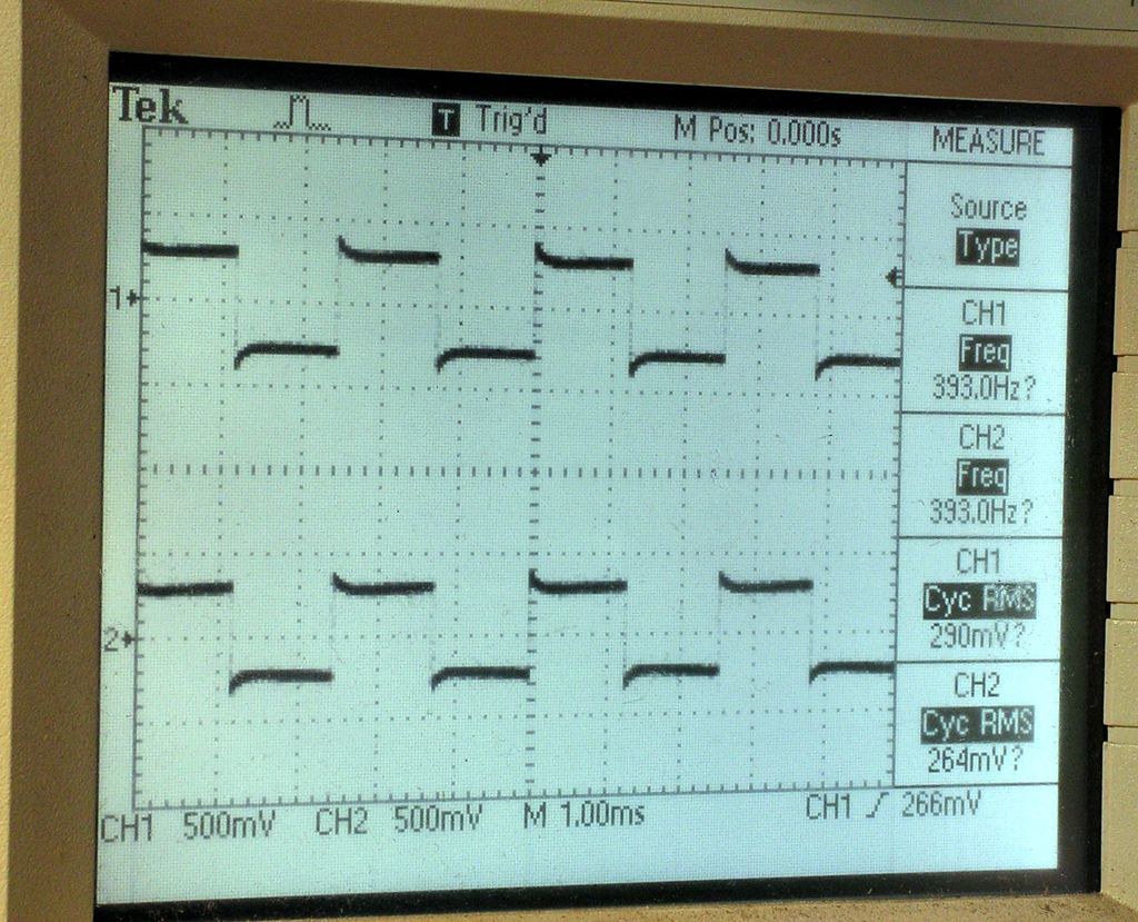
then TUNER input → 400Hz → Square → Tone Control Off → taken from speakers connectors
TUNER input → 400Hz → Square → Tone Control on → taken from speakers connectors
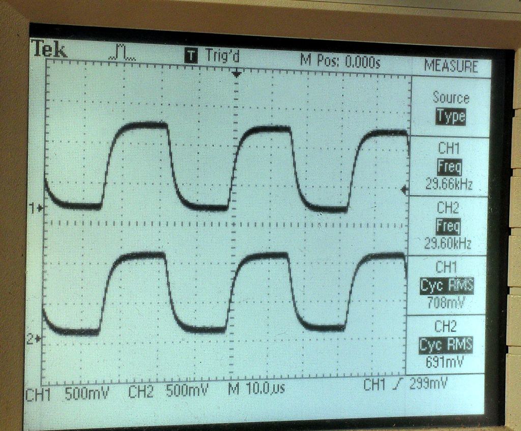
TUNER input → 30kHz → Square → Tone Control off → taken from speakers connectors
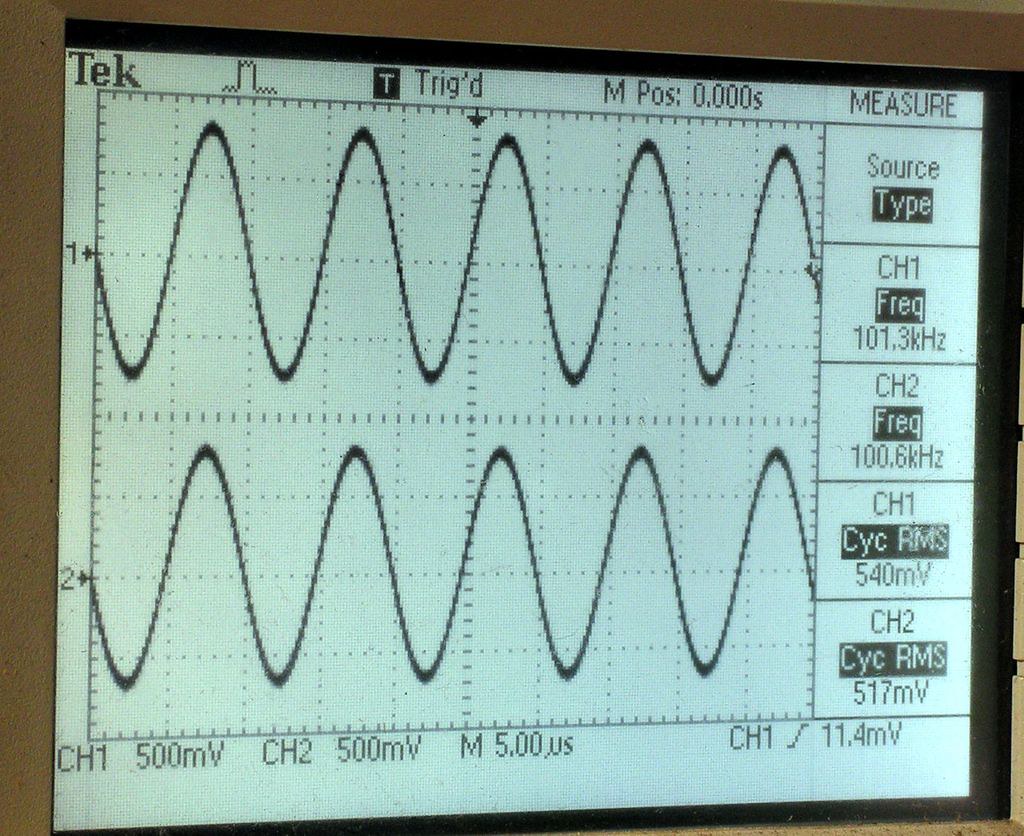
TUNER input → 100kHz → sinus → Tone Control off → taken from speakers connectors
All test signals was taken with dummy resistors 8 ohms 250 Watts connected on speakers terminal.
I did a clipping test (again with 8 ohm dummy resistors on speakers connectors), and it has just 90.6 w just before clipping which
