Restoration of 9090 non DB receiver
Here it is one big restoration on Sansui 9090 (non DB) receiver. I am going to show you so many interesting pictures at this thread… so….
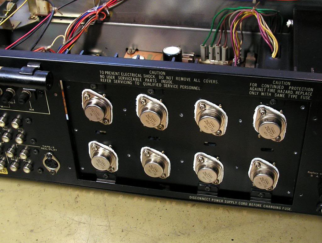
As you probably already know, 9090 receiver has quasi- complementary power stage with 8 pieces Sanken 2SC1116 TO3 NPN transistors, so it is not the same as 9090DB which has complementary output stage with 4 PNP and 4 NPN TO3 transistors.
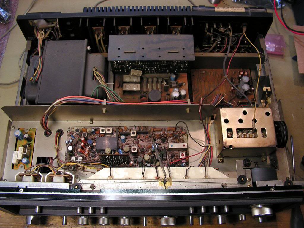
Receiver was in good shape, but not so clean, and with big problems with contacts on potentiometers and switches and selectors.
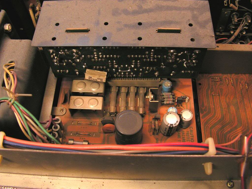
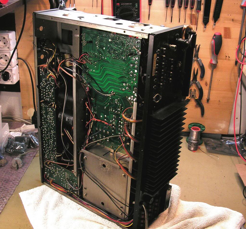
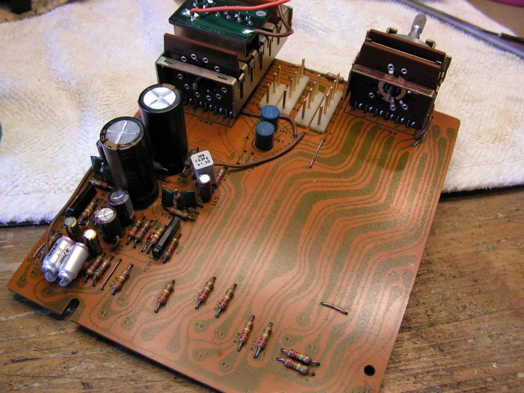
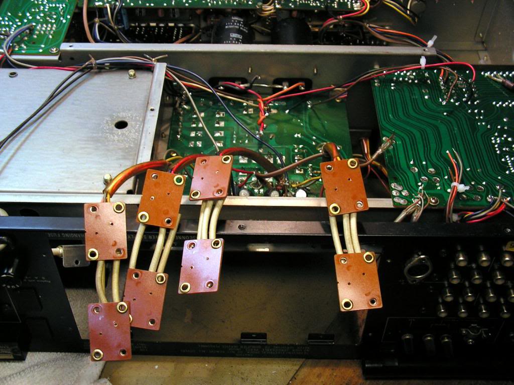
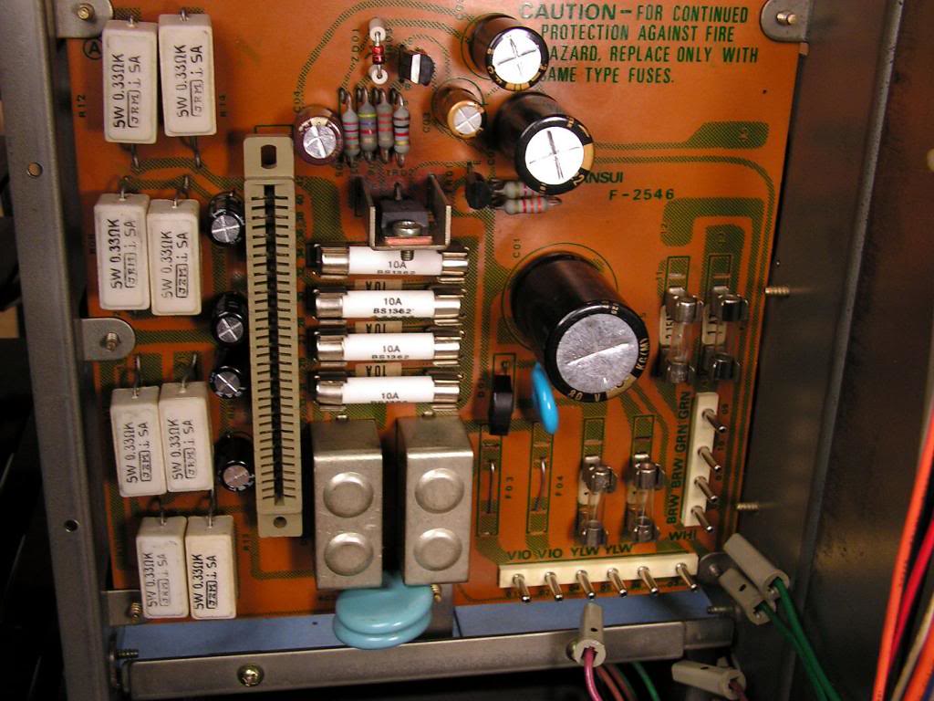
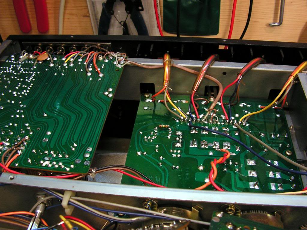
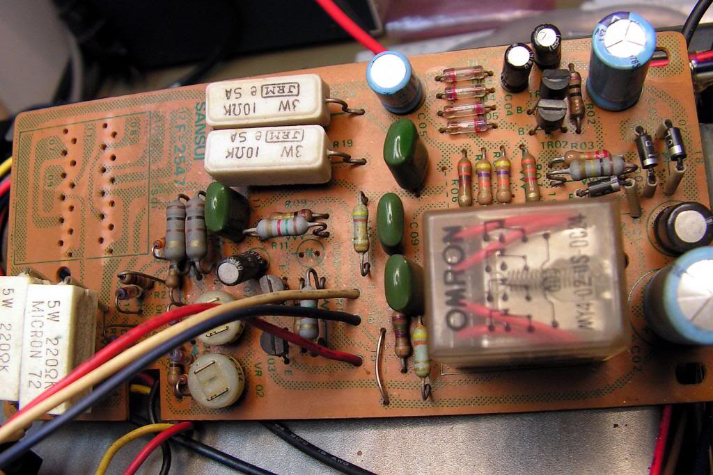
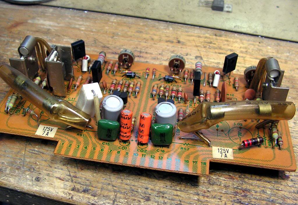
… power supply board and driver board…
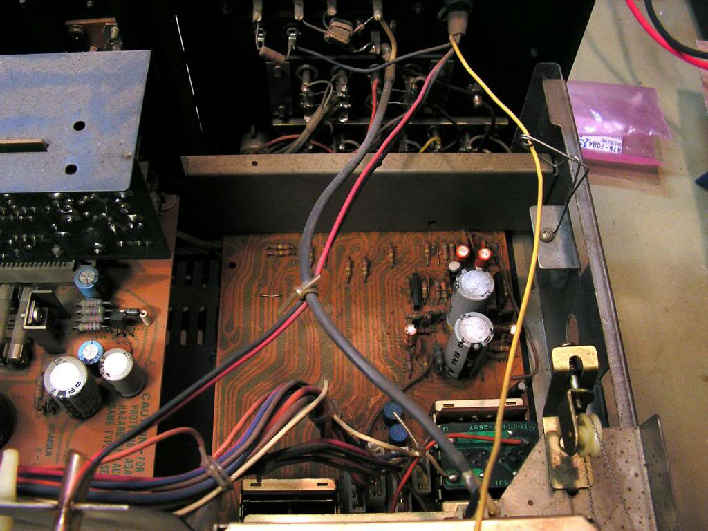
… phono preamp…
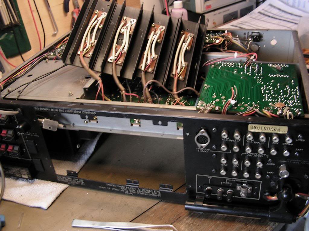
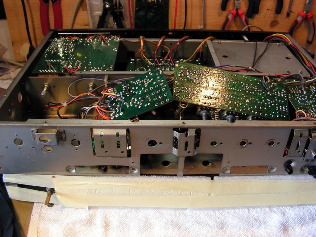
… driver board pulled out…
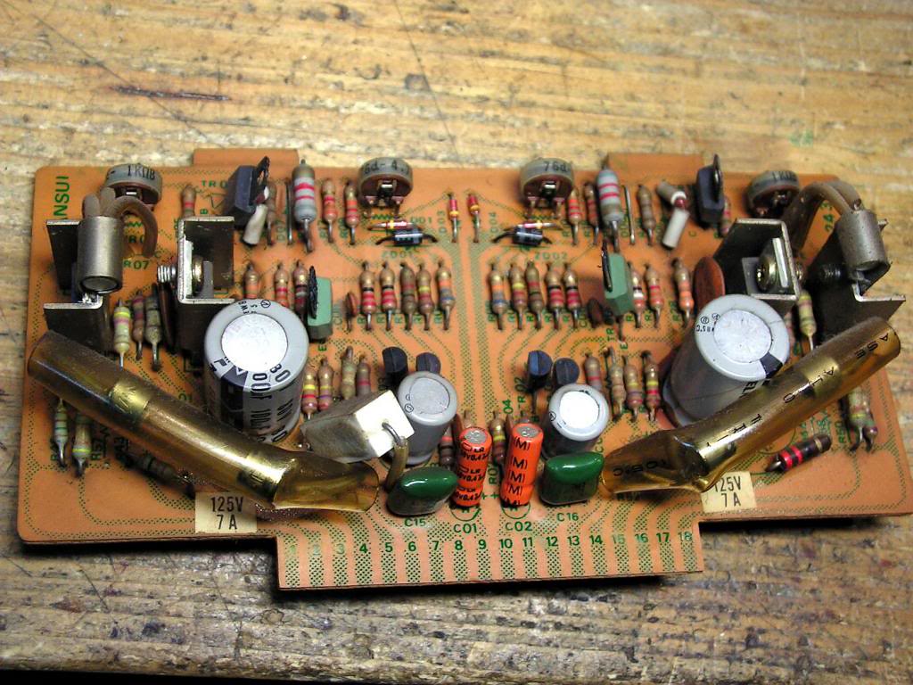
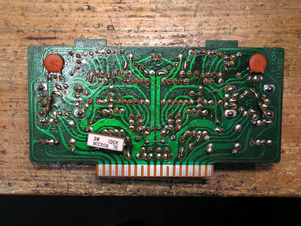
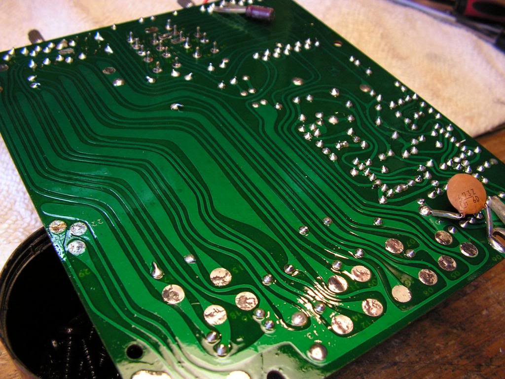
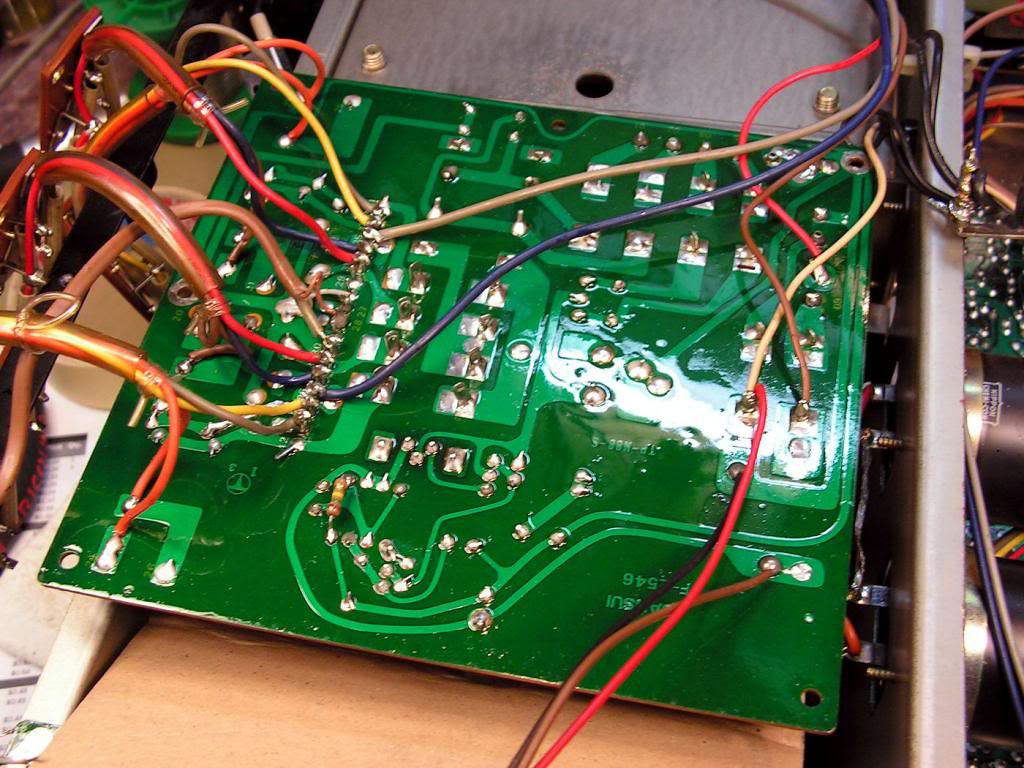
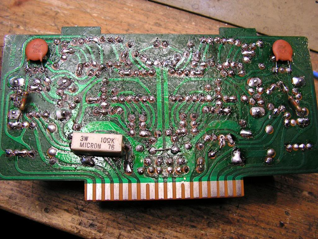
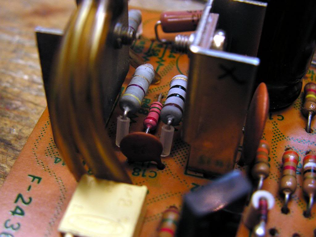
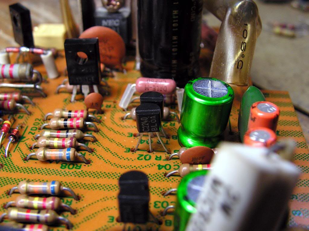
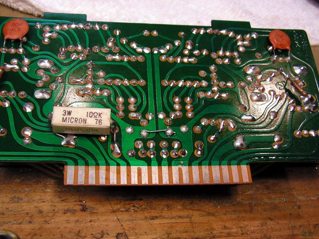
… another side of the driver board… I know that it will be a lot of work on that board… but about that, later…
So, let’s get started dismounting receiver…
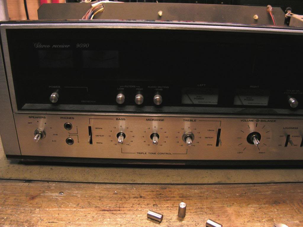
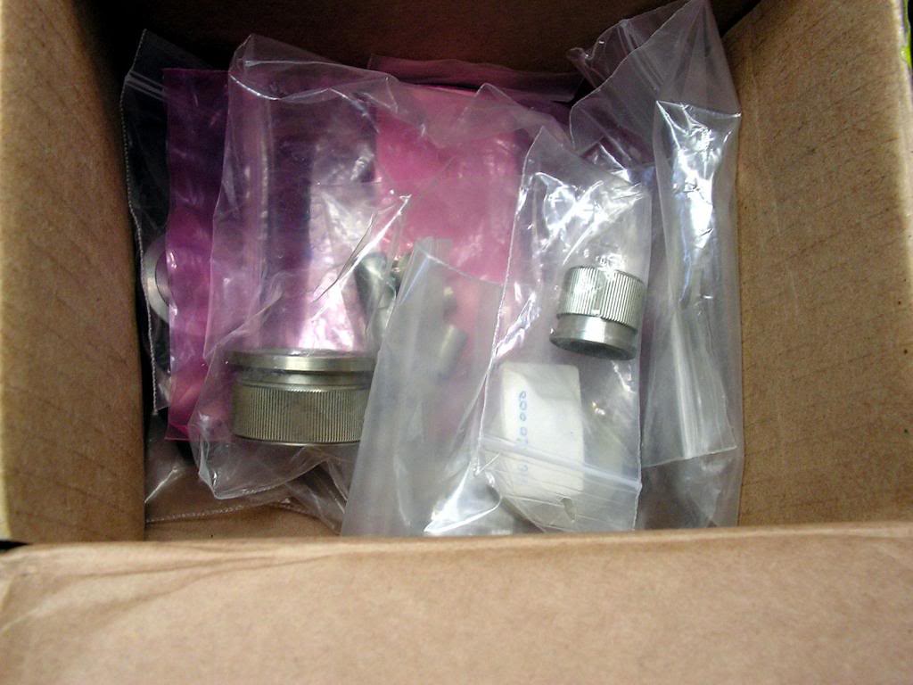
I like to protect knobs against damage, so every knob was at separate small plastic bag..
… And finally, “naked” receiver…
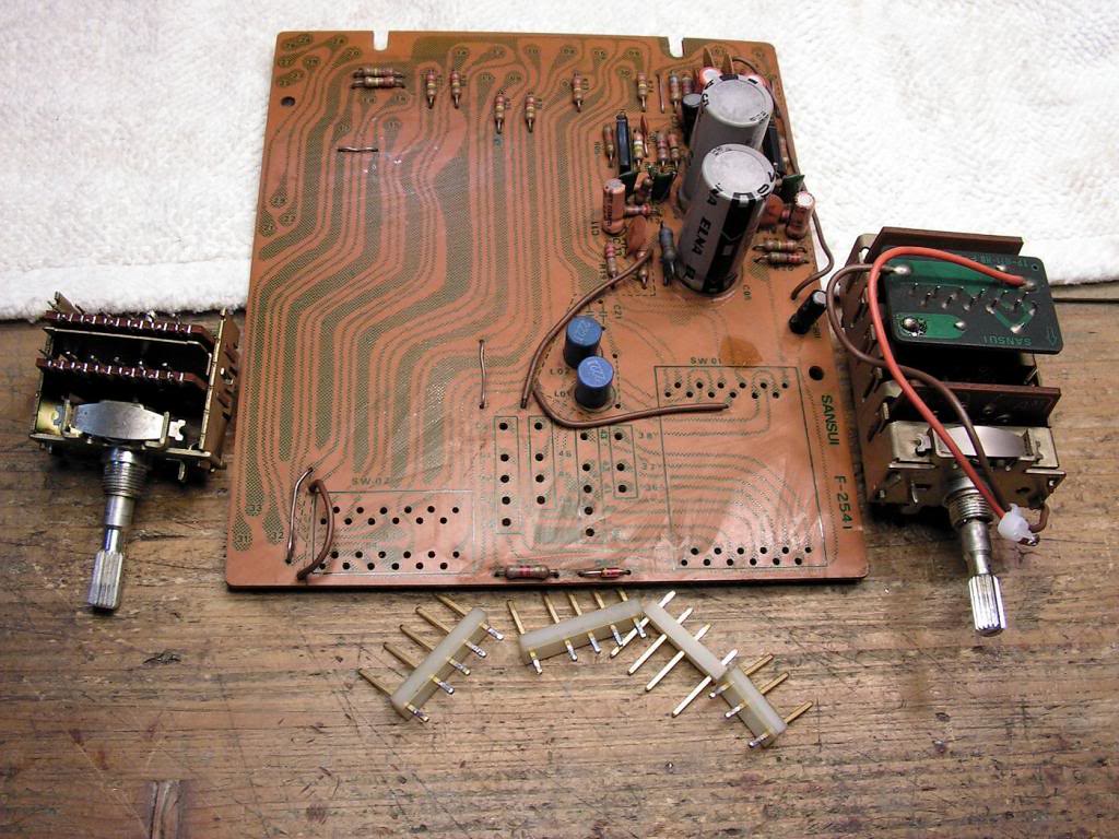
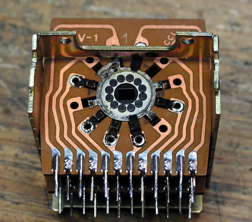
First board, on which I started restoration was Phono Board with input selector… because it was very dirty, I have to dismount almost everything to clean those parts properly
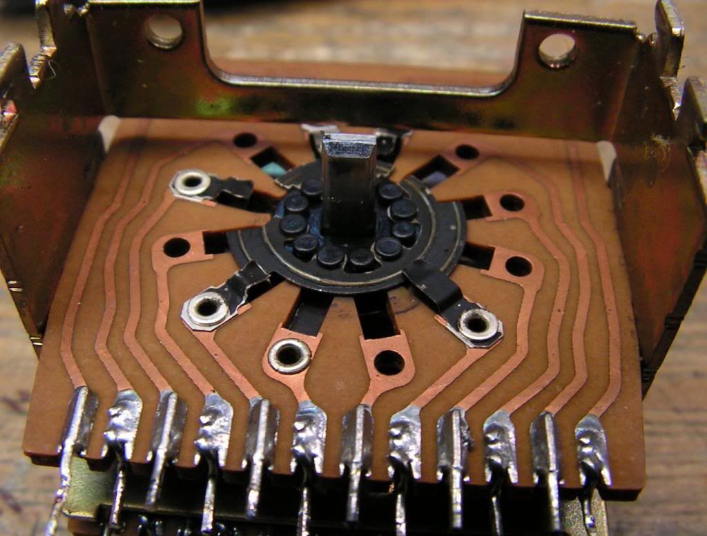
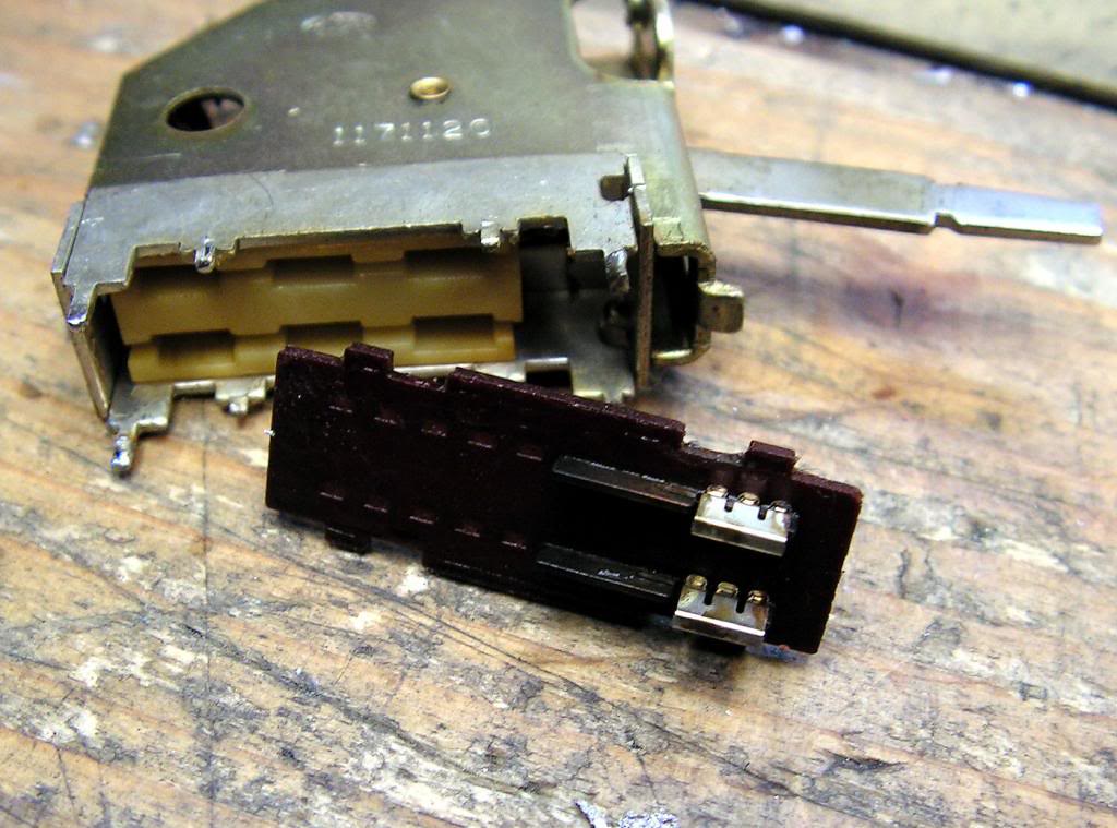
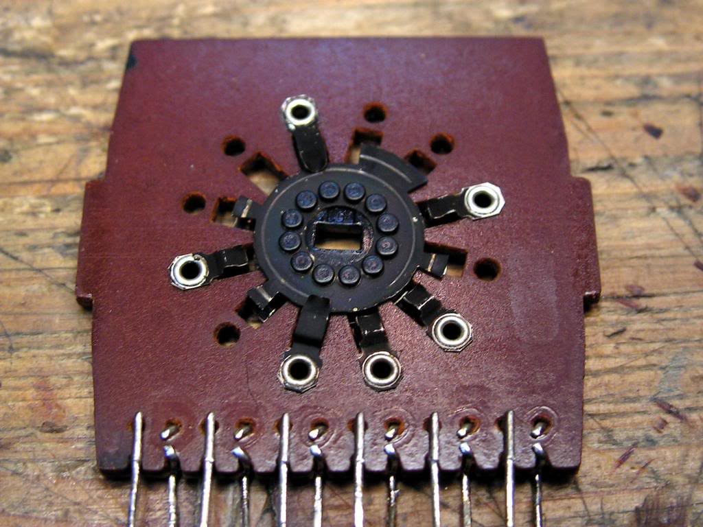
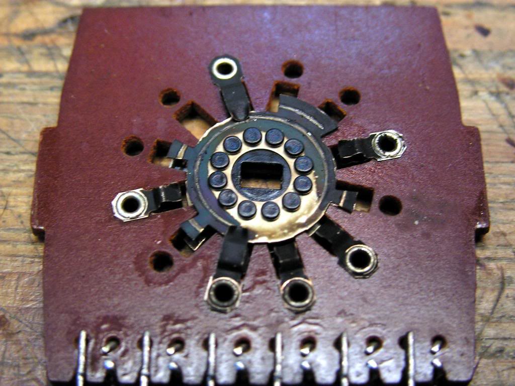
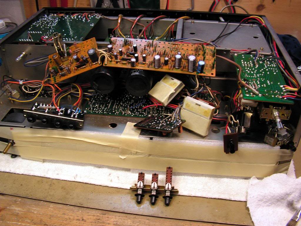
… first… Input Selector…
… and cleaned…
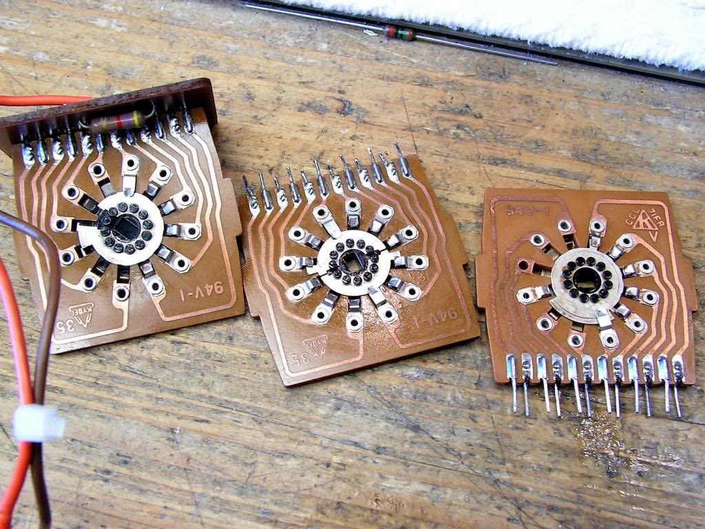
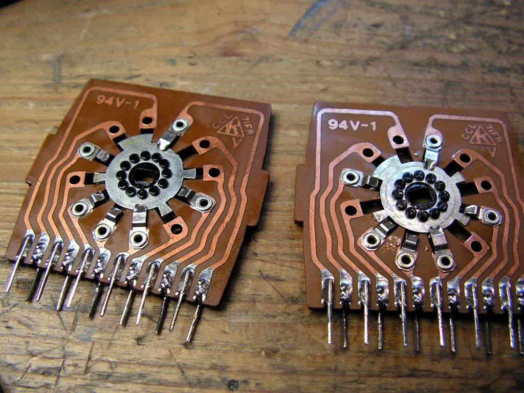
… then, Tape Selector…
… and cleaned…
… another cleaned side…
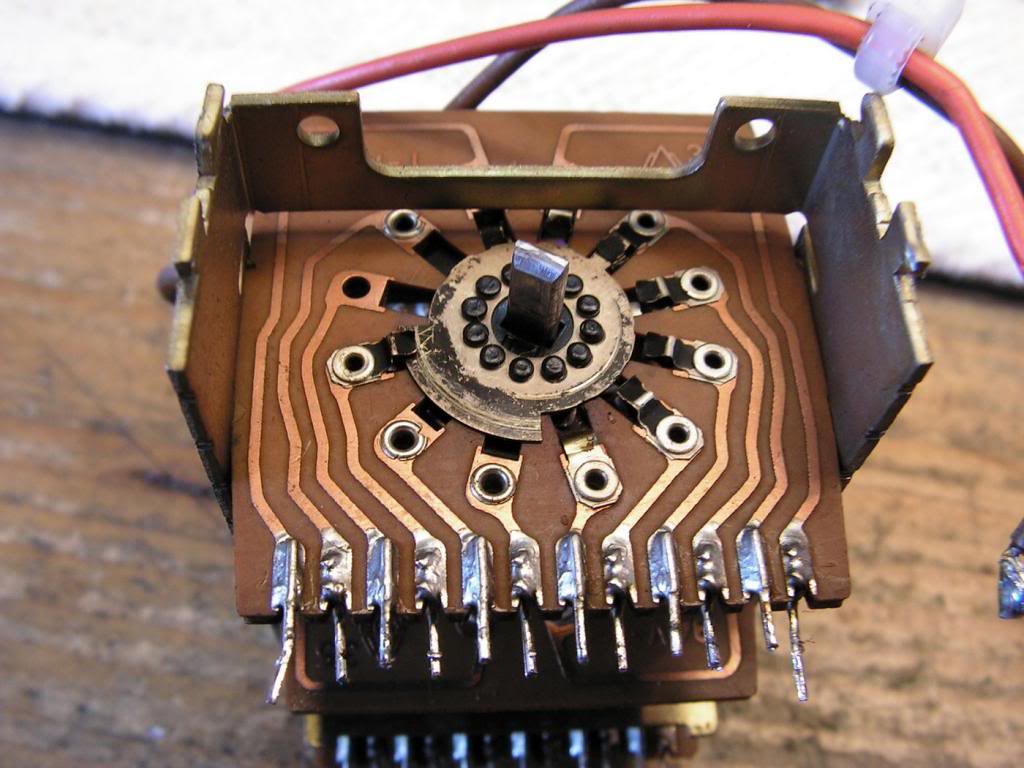
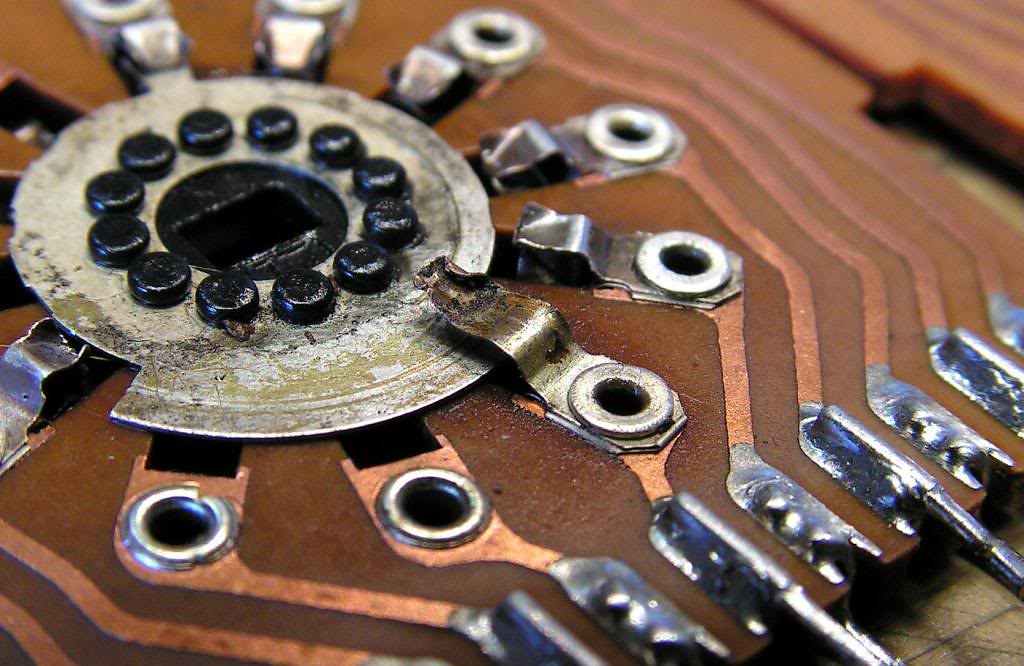
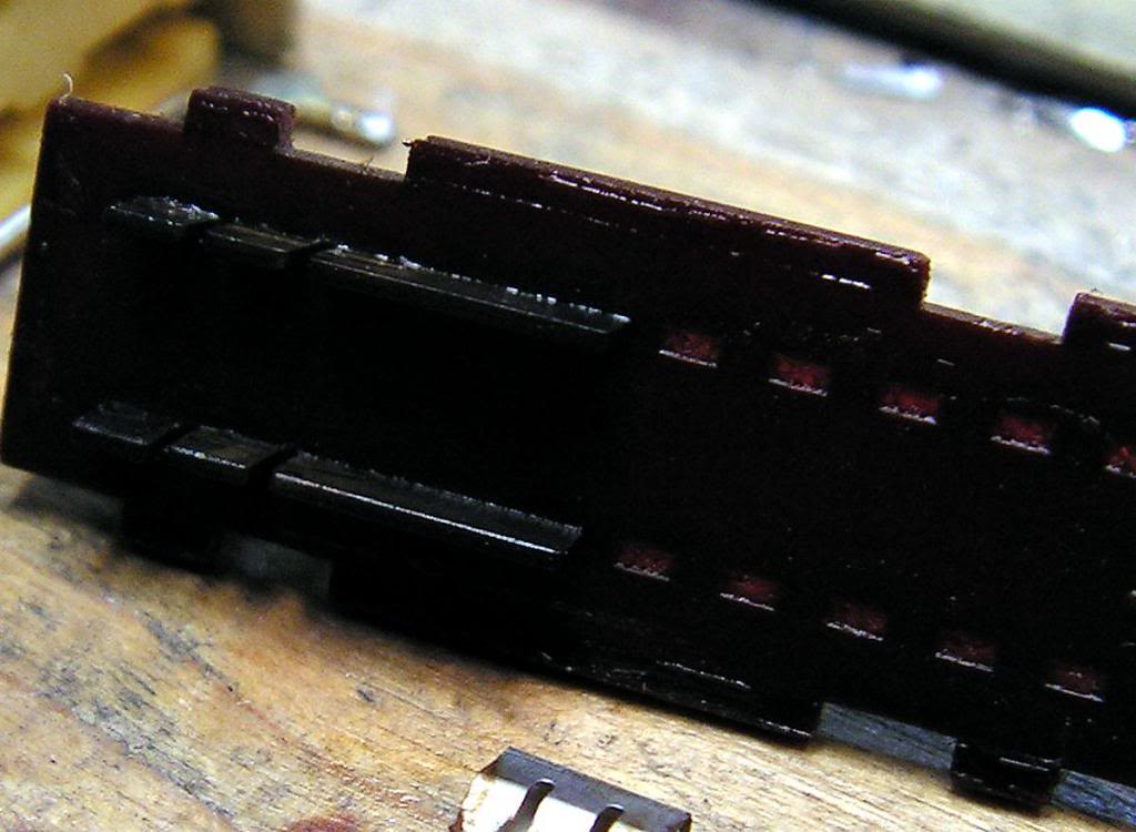
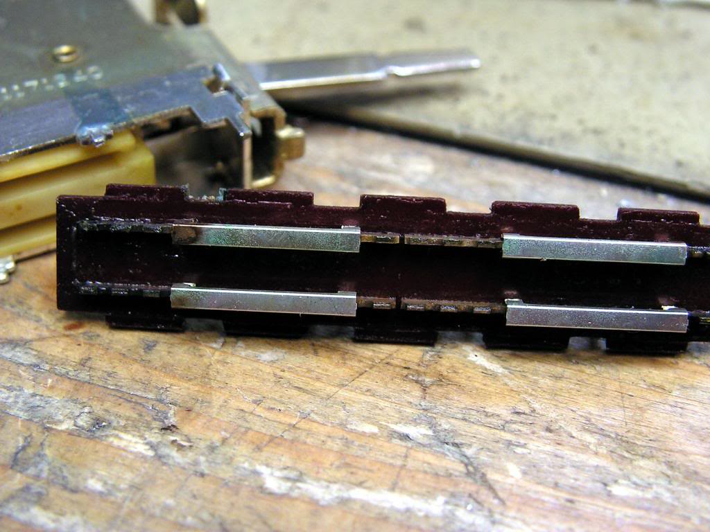
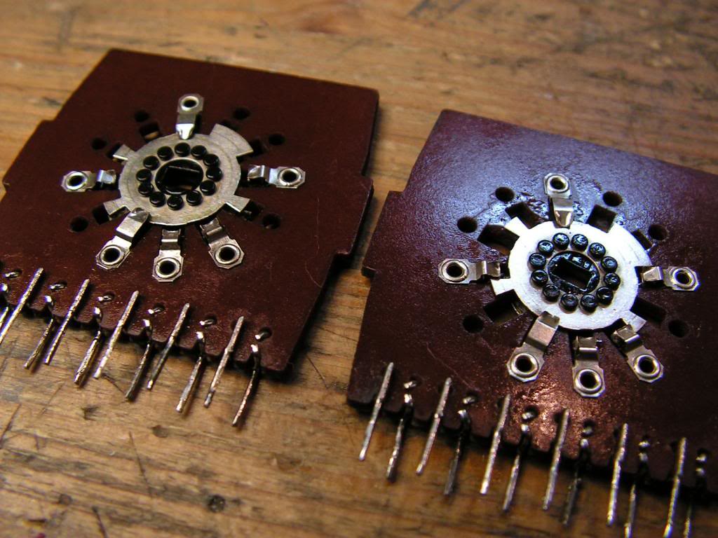
BUT we will go back on the picture of Input Selector…
Do you see anything wrong here?
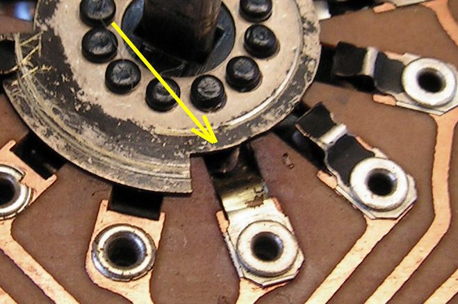
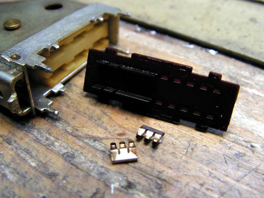
No? OK, please look at that detail…
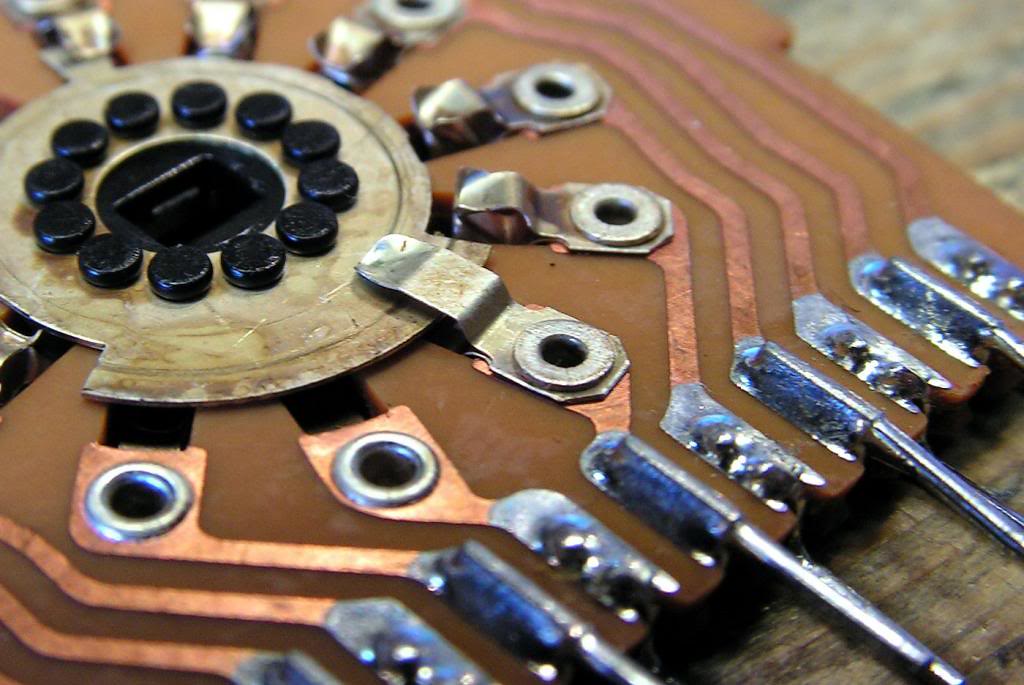
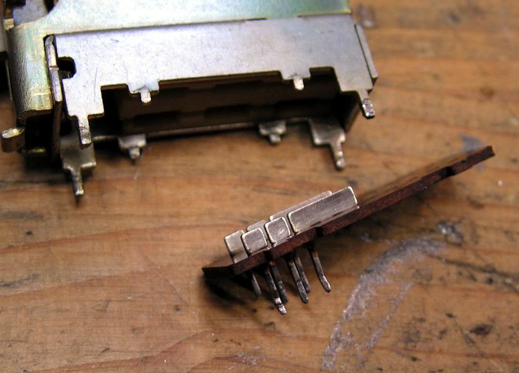
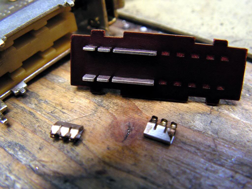
That contact was bent!!! I really don’t know how?!? I tried to fix it, but without good result!
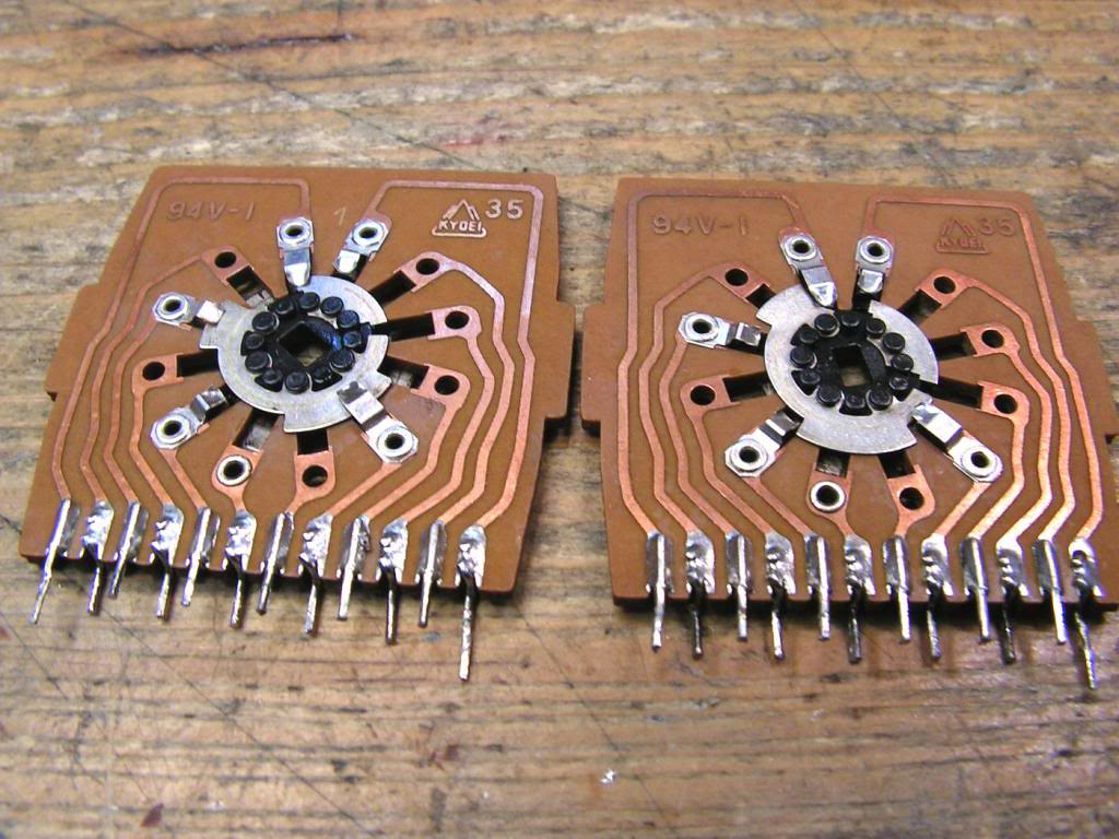
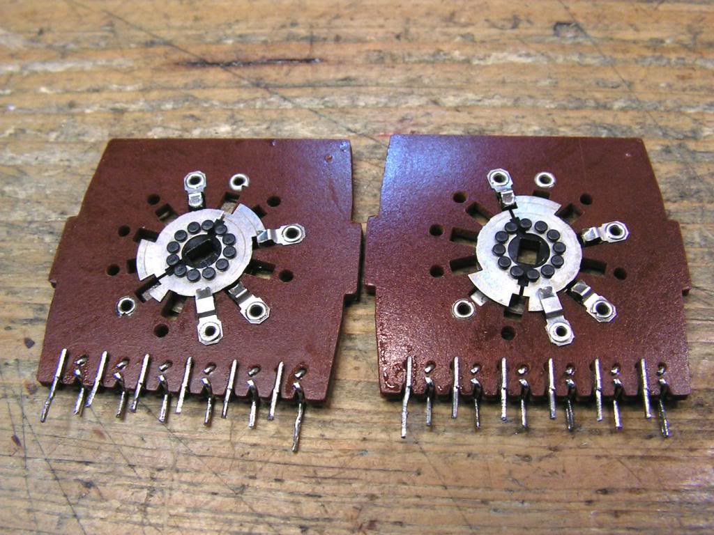
… and, I was lucky… at my stock I had a NOS input selector, so I replaced that wafer (not all selector, just that wafer)
And that first board was restored…
Normally, I resoldered every solder point, and covered with new layer of colophony (rosin).
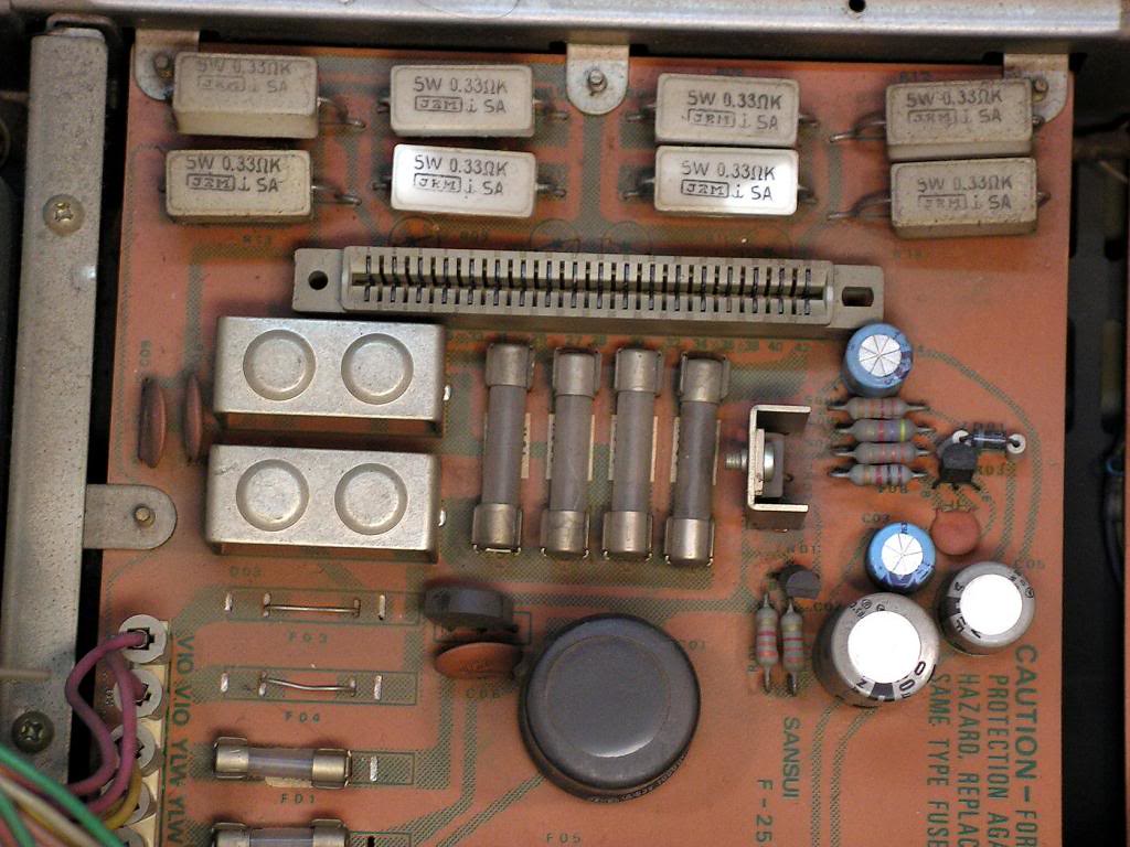
And now, the Power Supply Board…
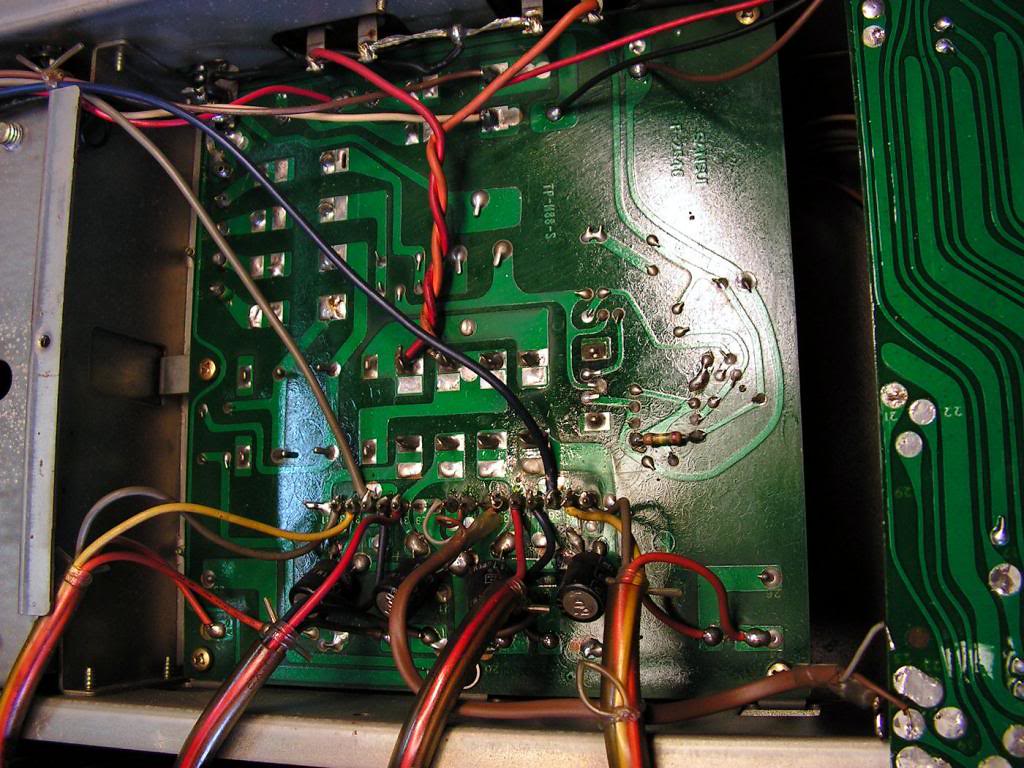
… another side…
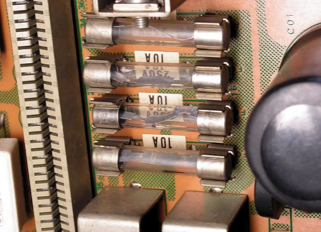
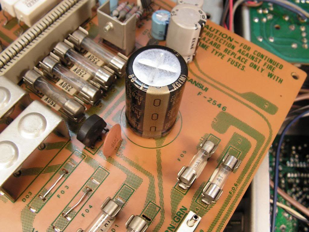
Those fuses should be replaced because I think they are old car fuses, I would replace them by ceramic 10A fuses
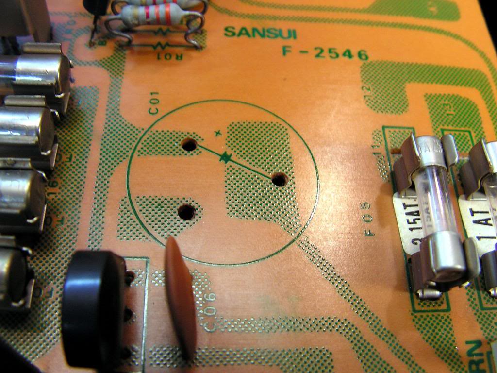
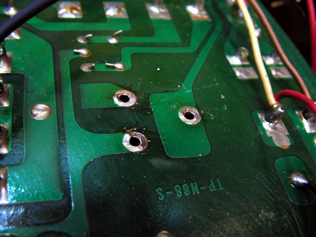
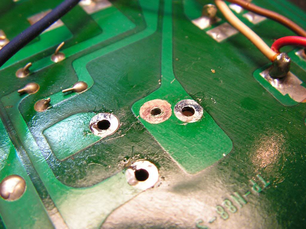
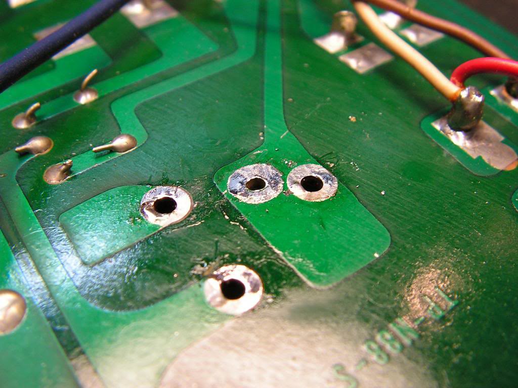
… there, I had a problem with that 1000uF capacitor. It was with three legs, and new one what I have is smaller and with two legs…
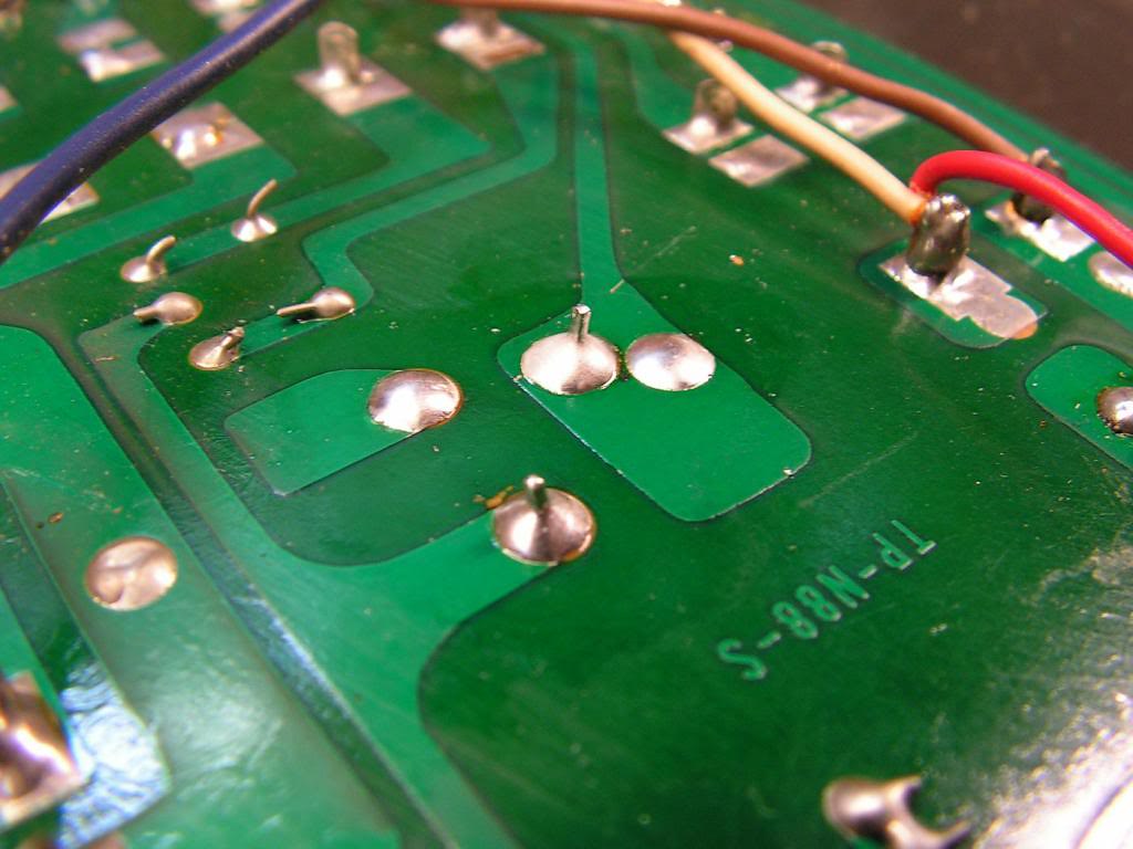
So, I made a new solder point for that new smaller two contact 1000uF capacitor
… and the result is here…
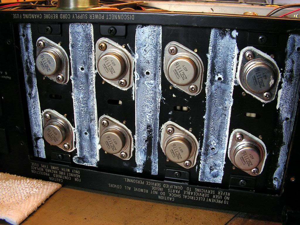
And, here they are 8 pieces of Sanken 2SC1116 transistors…
I must dismount all because I must clean all those parts…
And finally TO3 sockets…. Ready to clean
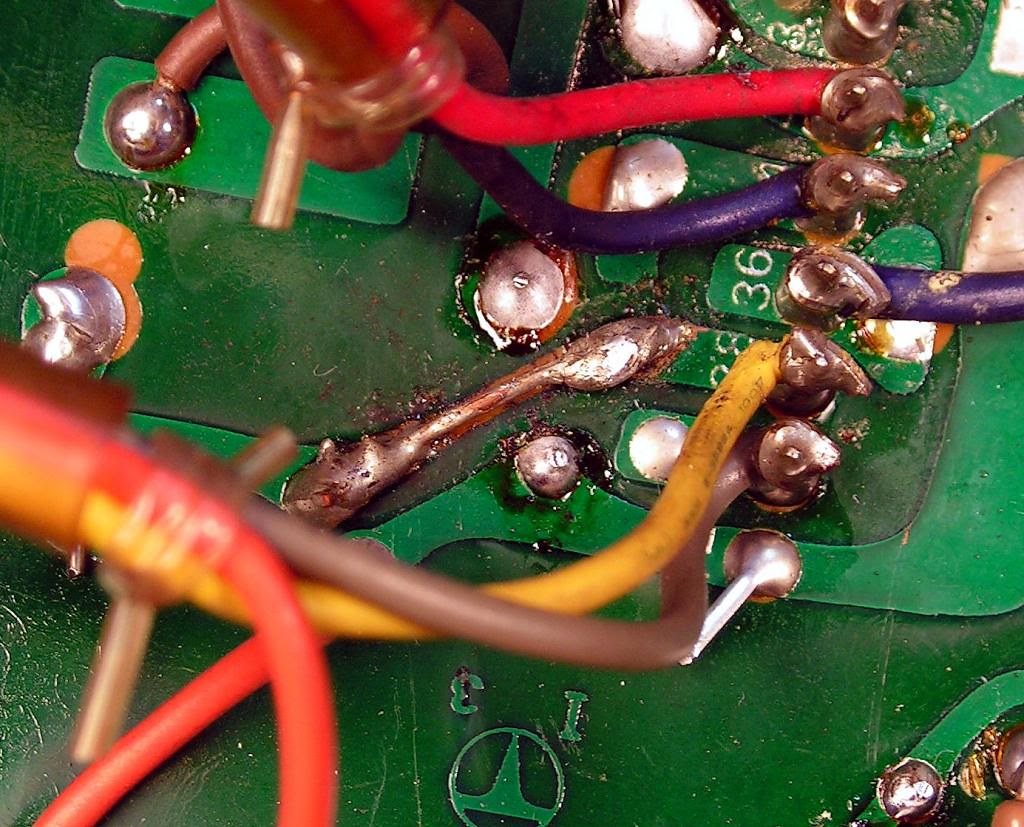
That power board is, on the same time, the mother board for driver board, so it had some burned damage from the past, and it was not fixed nicely, so I tried fix that damage on better way… not excellent, but just better way… so how it was:
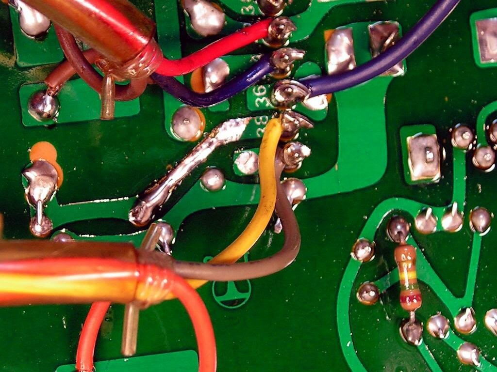
And how it is now…
… those bipolar capacitors that were soldered on the back side of that board (probably because they will be in touch with those ceramic emitter resistors… heat problem) I soldered back on component side, because my bipolar capacitors are smaller than those older.
And you can see them just beside of connector for driver board
And the first two restored boards are on their place
Now, we are going to the front of the receiver…
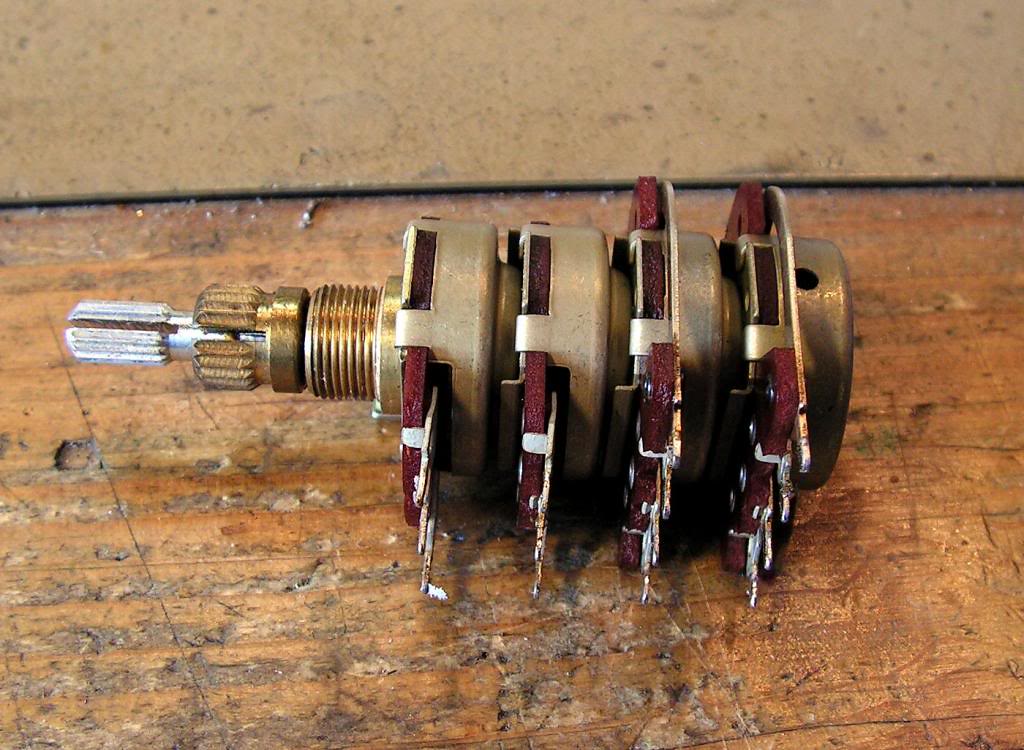
First job what I will do is deep cleaning of volume – balance potentiometer, because it had a big problem with bad contacts…
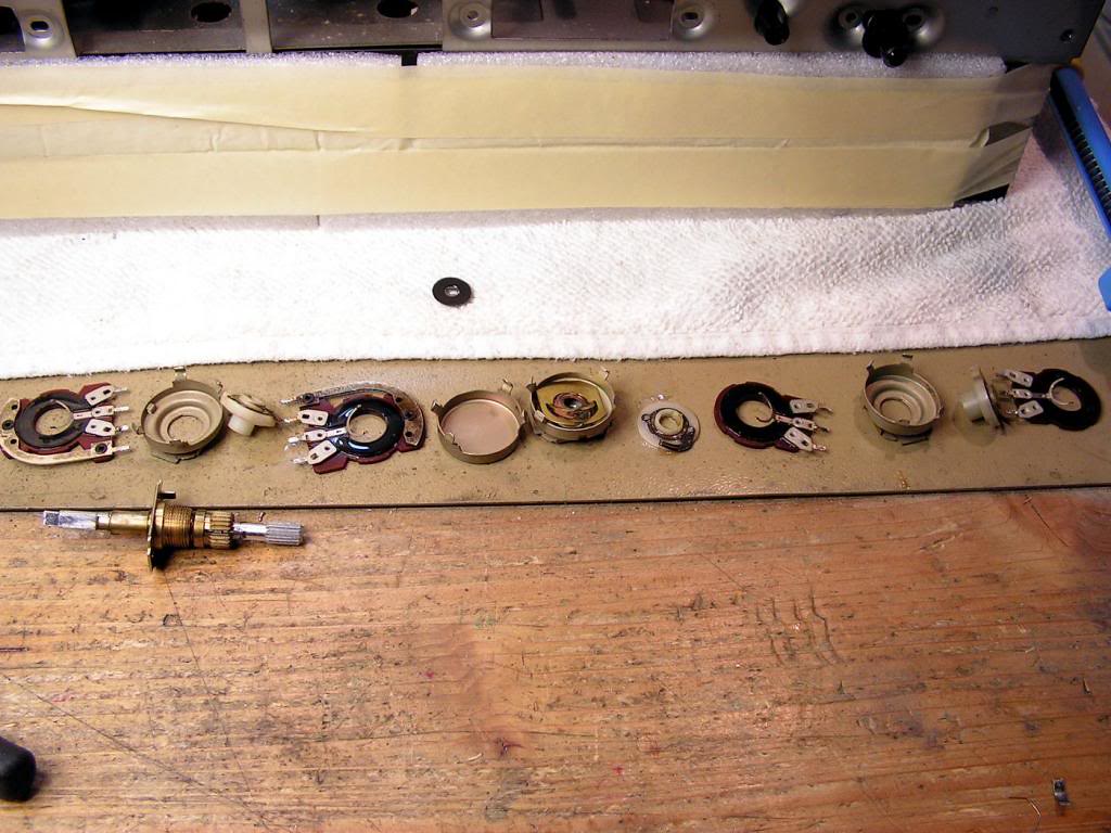
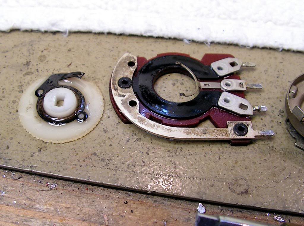
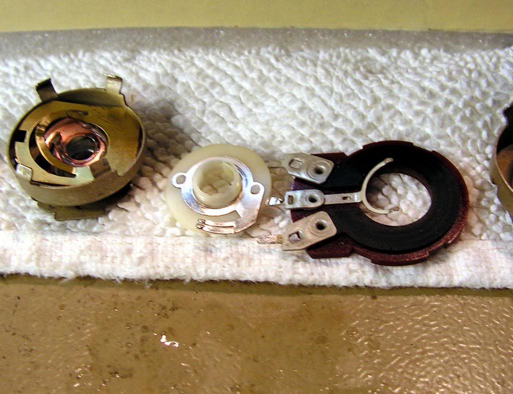
It is not easy to dismount, but finally on the next picture you can see all parts of that potentiometer
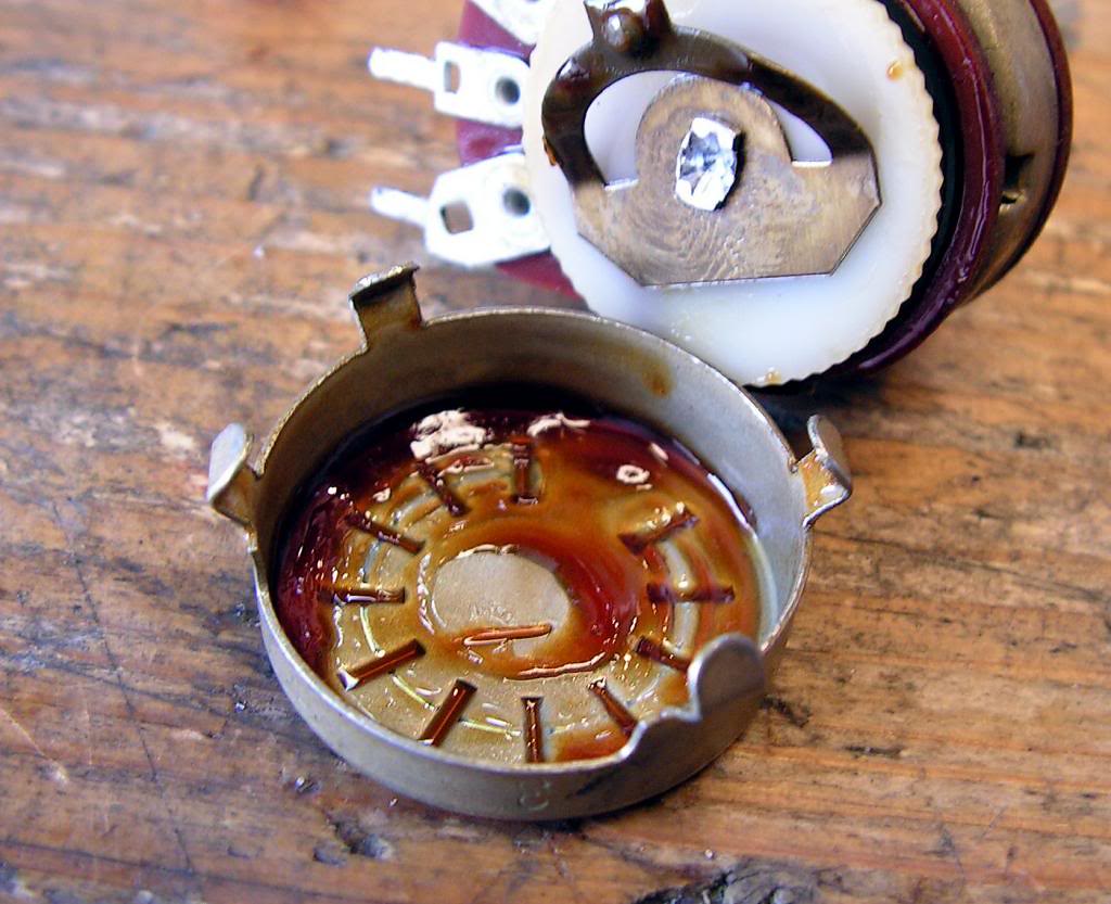
… and please look how dirty it was….
… and after cleaning…
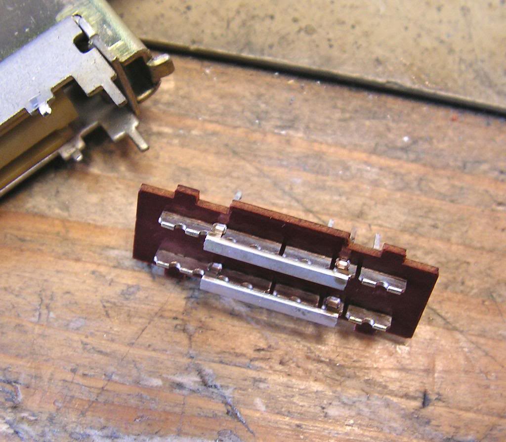
The same thing with switches…
… close view…
Another dirty switch…
And how I cleaned them….
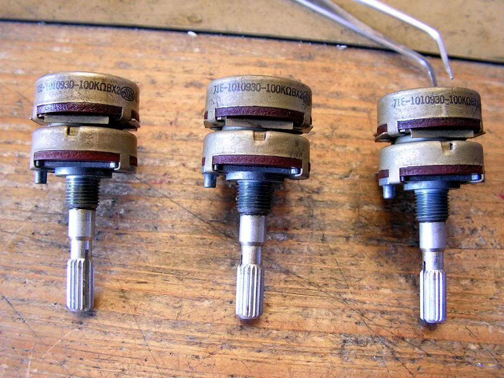
And now tone control potentiometers
As I already written, it is not so good to use contact cleaner without open those potentiometers, because those potentiometers has some grease inside of them, and that contact cleaner can make things worse if that grease finally arrived at potentiometers contacts
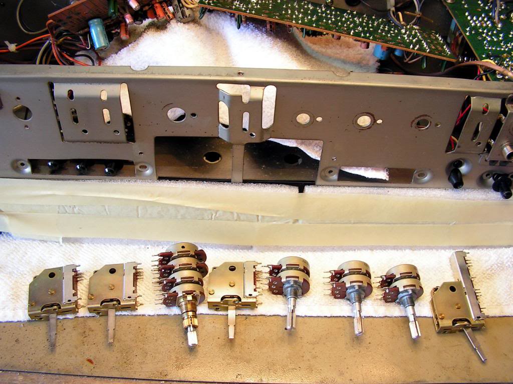
Finally what I have cleaned until now…
I wish to show you something… It was one thing which can make me a big trouble during dismounting switches from boards, please take a look at the next picture
You see that bended switch pin? That pin was bent in the factory to fix that switch to the board before soldering, and if you didn’t remove all solder material from that point, you will damage solder point during removing that switch from board!
Another switches need to be cleaned…
And speakers selector…
And cleaned…
At this stage of cleaning, the receiver looked like on that picture
And there you can see tone control board finished…
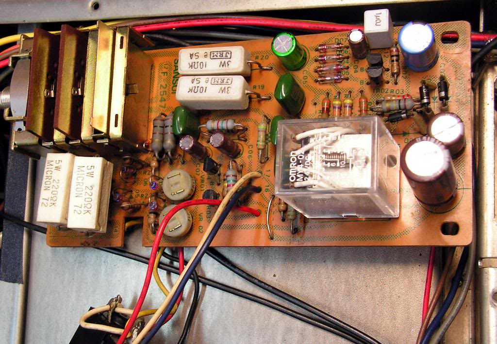
And finished the Protection Board with Speakers Selector
And how it was (missing Speakers Selector)
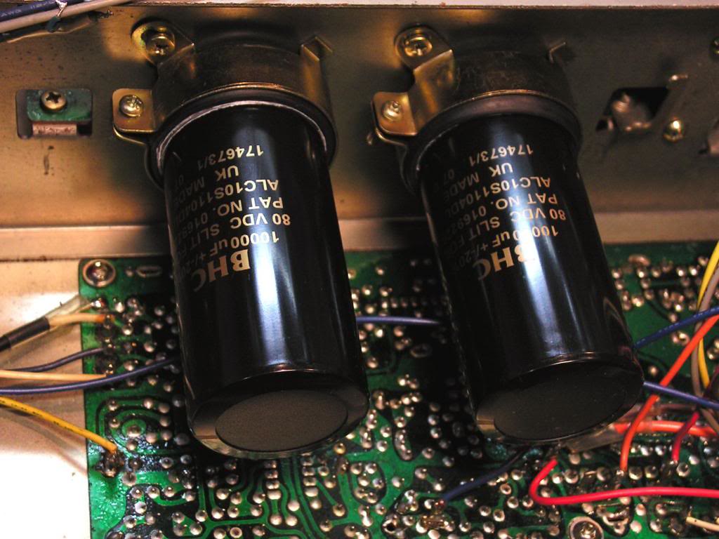
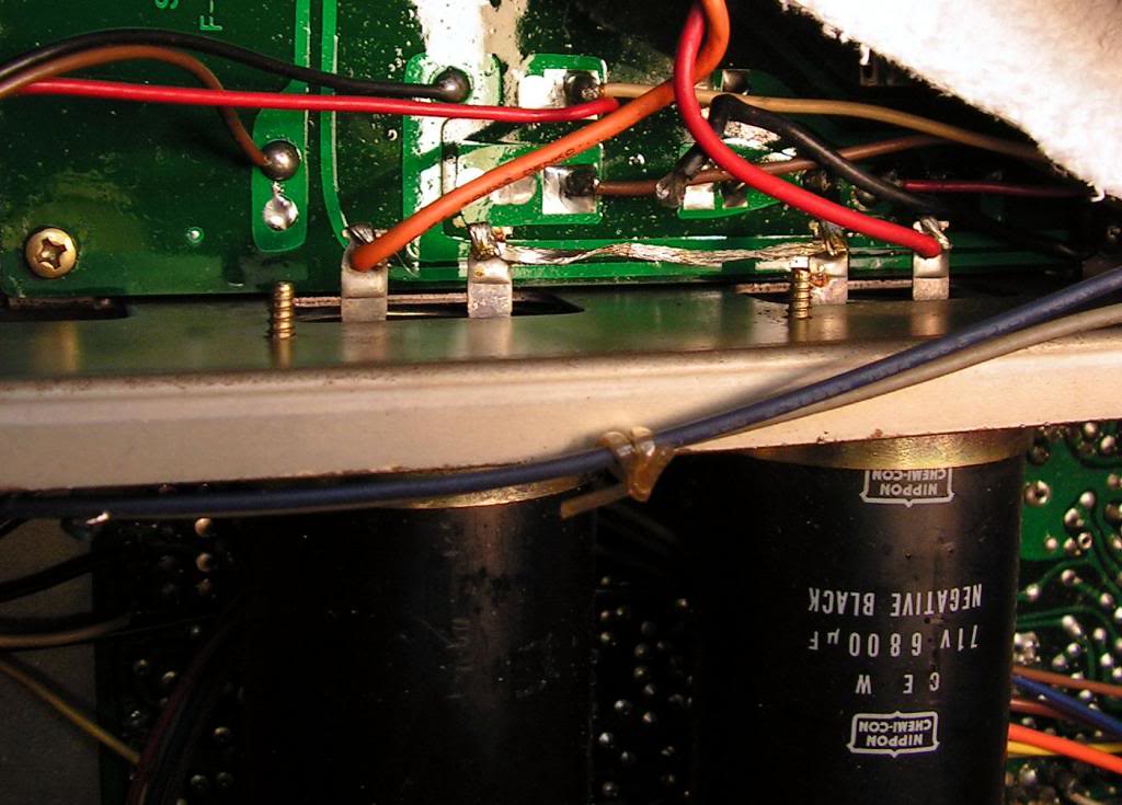
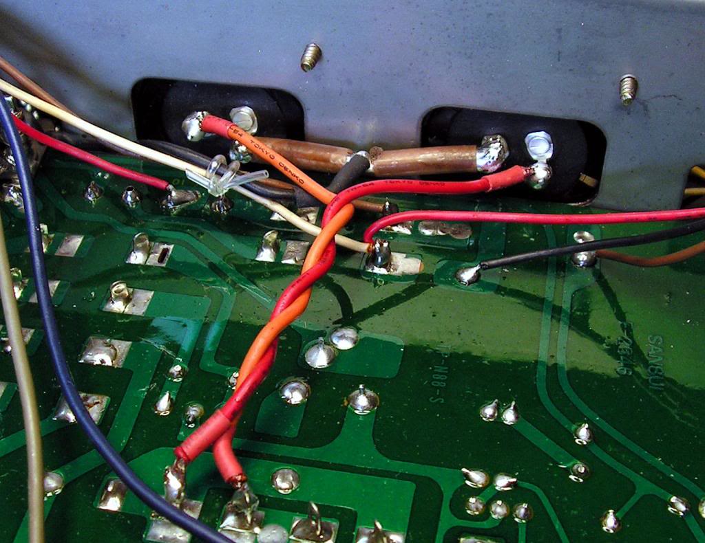
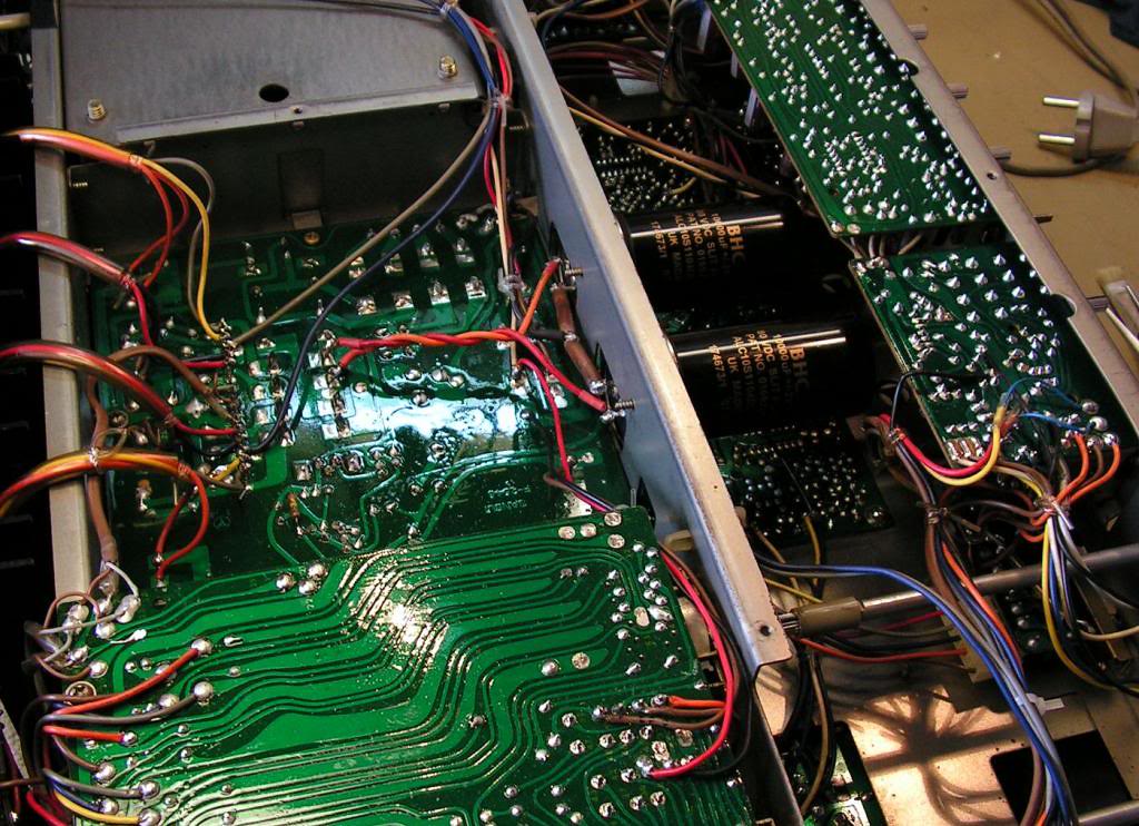
And now, how I installed a new main capacitors… The old ones was 6800uF 71V and with diameter 40 mm, I decided to install BHC Slit-foil capacitor 10.000uF 80V, but those new capacitors are 35 mm in diameter, so I have to adapt clamps to accept those new capacitors
On the next picture is wiring of old capacitors…
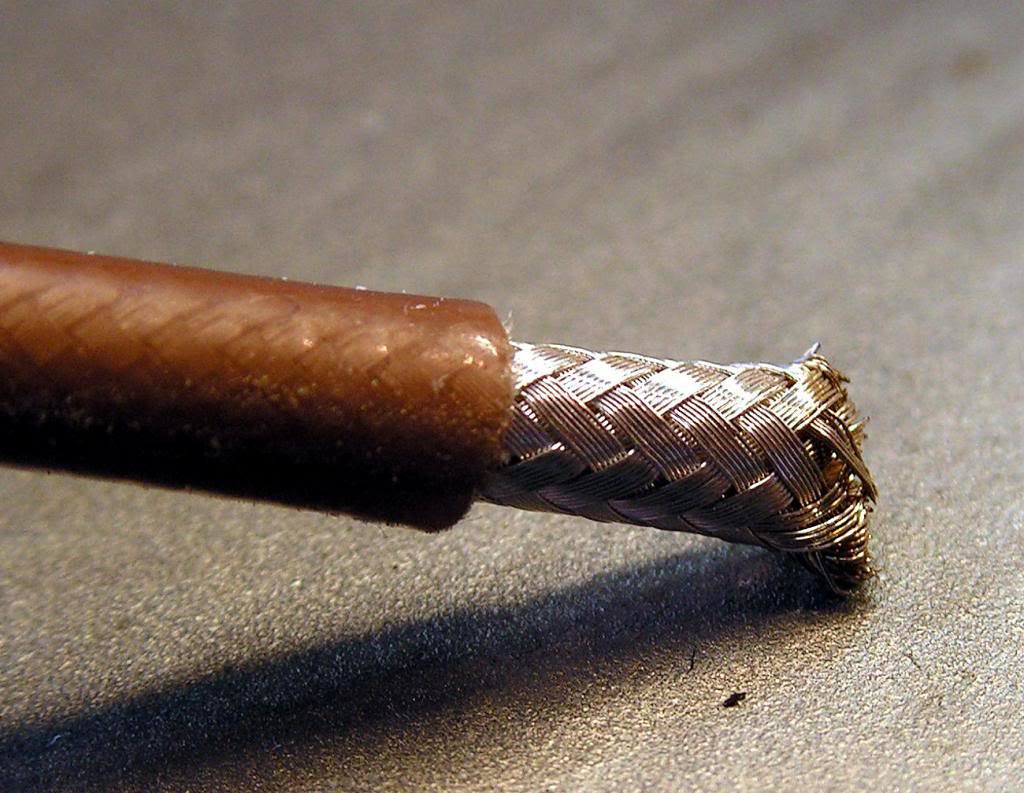
For connection capacitors to the Ground, I used that cable (from one coaxial cable)
And finally, now it looks like on the next pictures
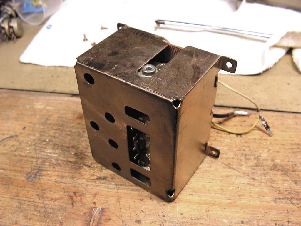
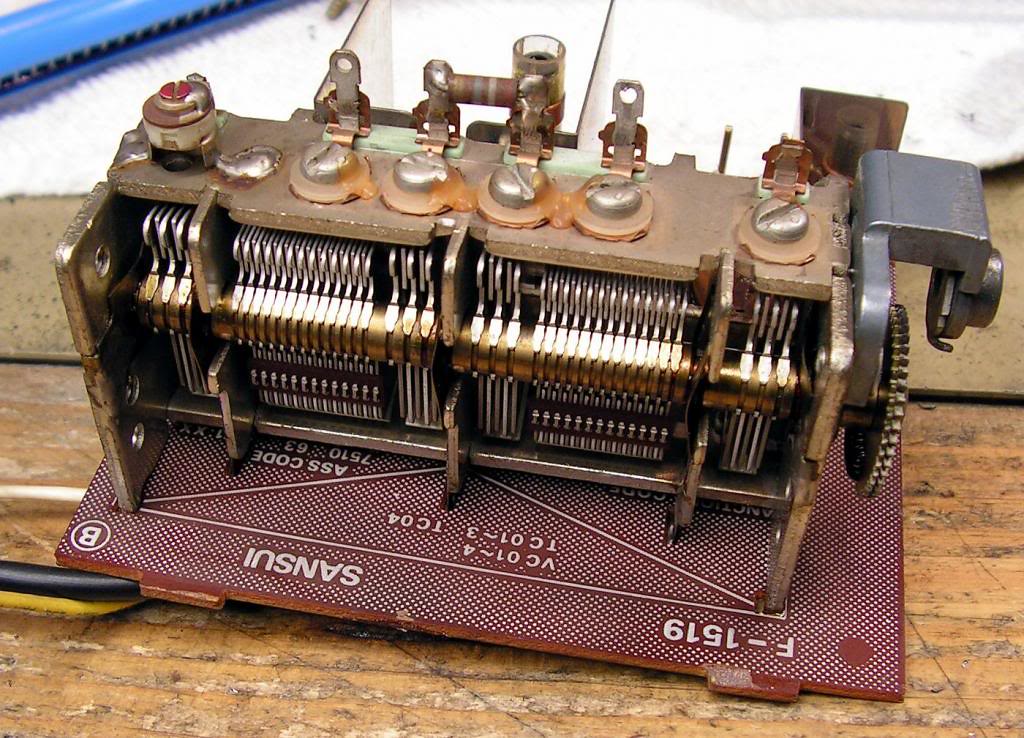
And now, very specific part… The Front End of tuner section… The first thing I had to do was to desolder the connecting cables
… and here it is…
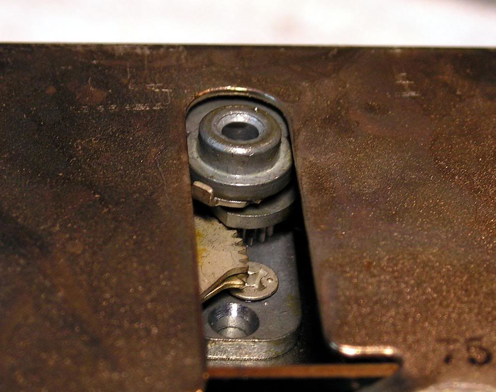
… on the next picture you can see one detail, mechanism for rotation of capacitor, and you should be very careful with that…
… now, it is out… and I can clean with deoxid contacts to the ground, which is very important for proper work of that part
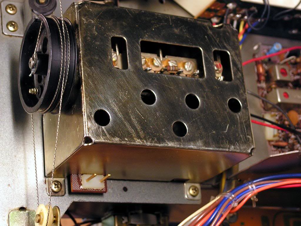
… installed back…
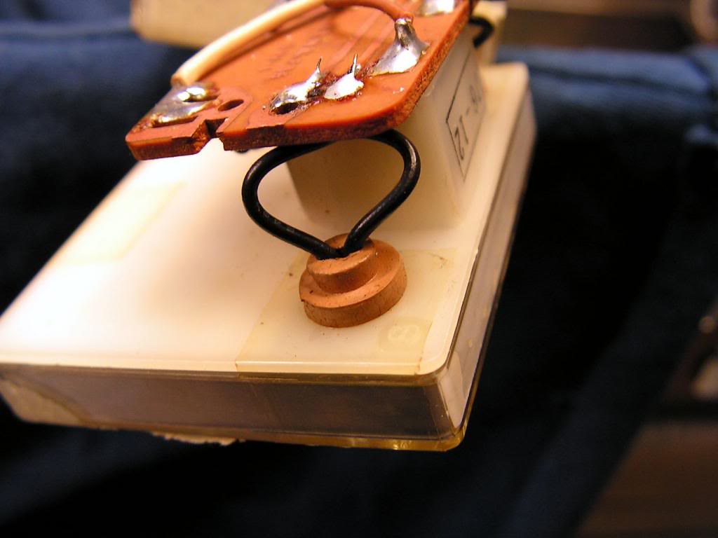
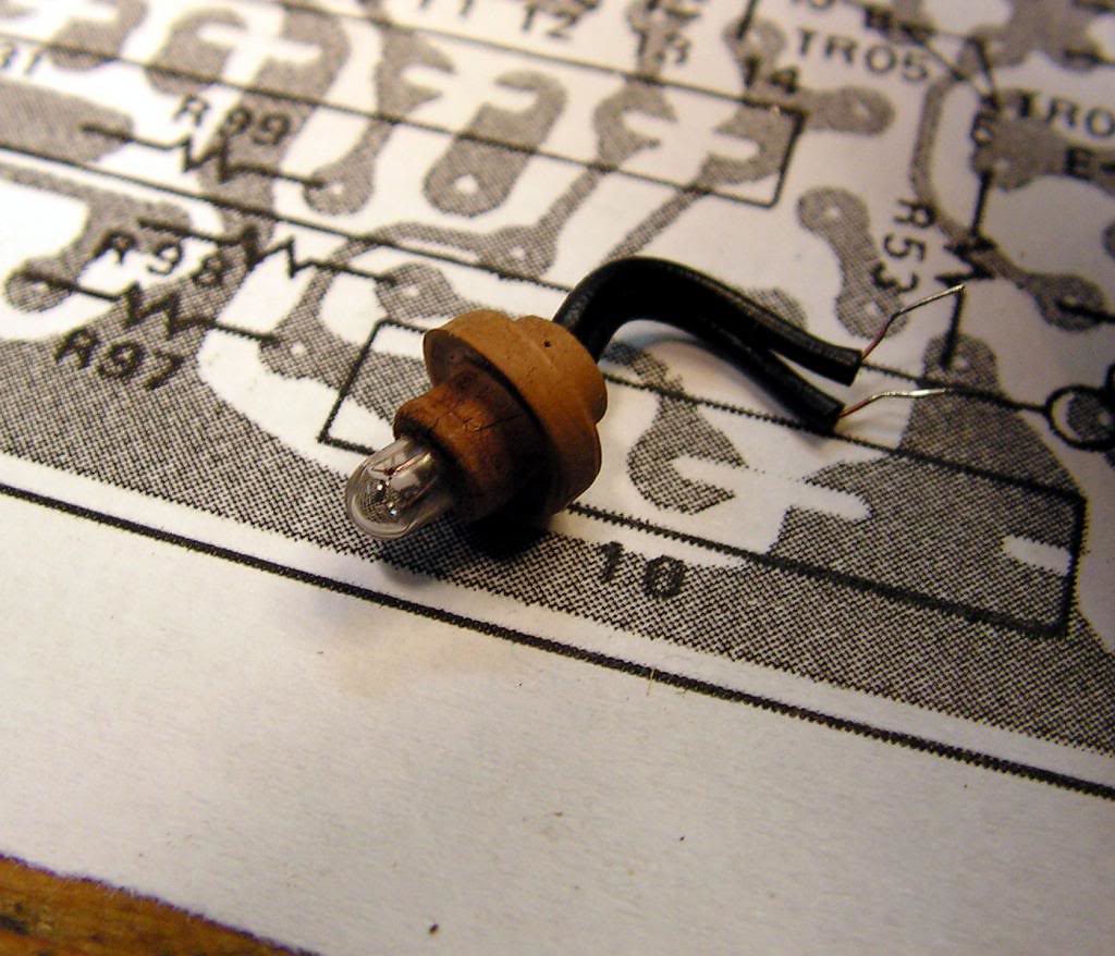
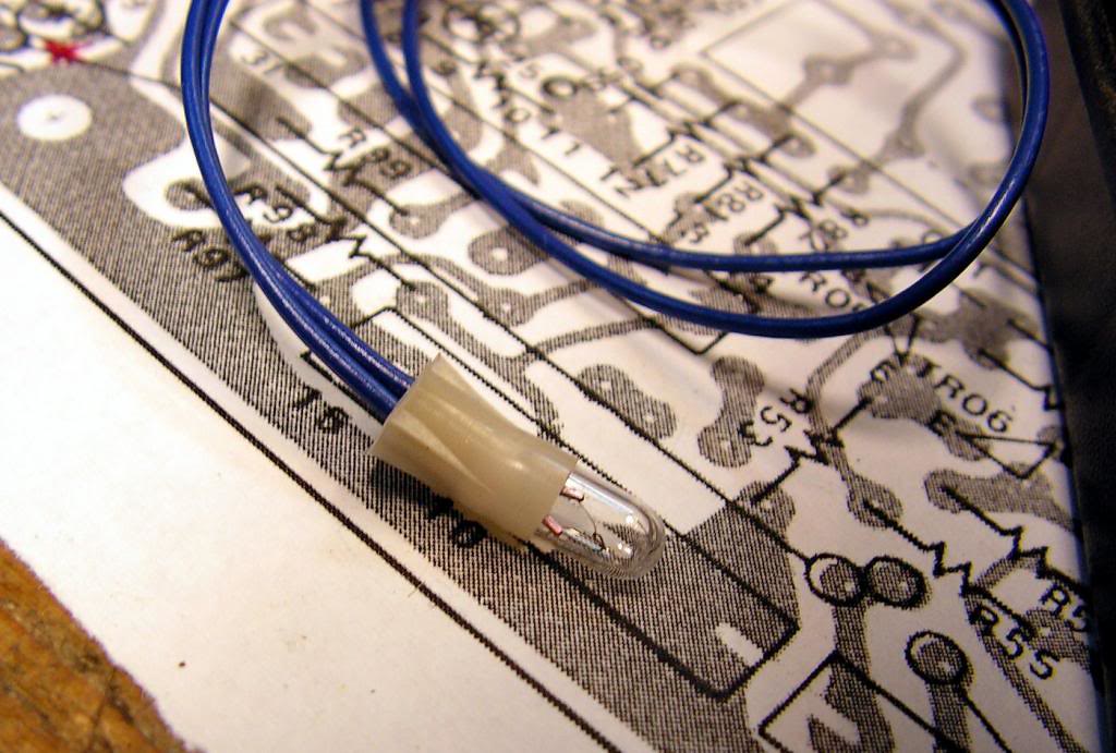
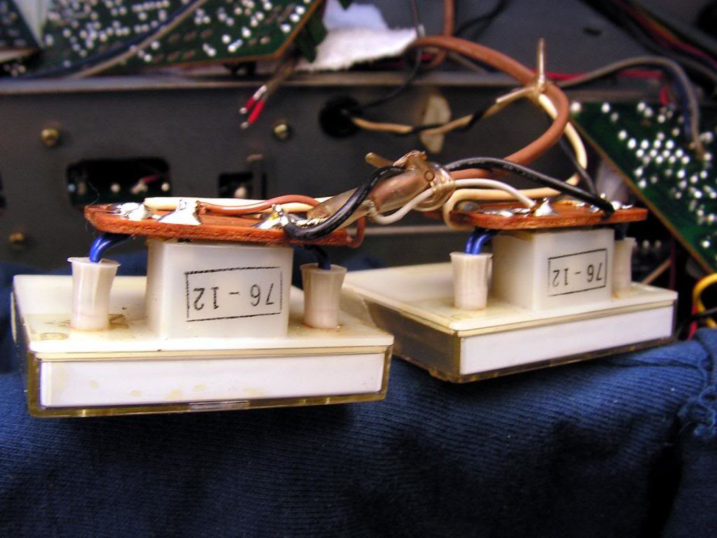
Now… changing back-lighting of the power meters, very hard to do…
The old bulb…
New bulbs…
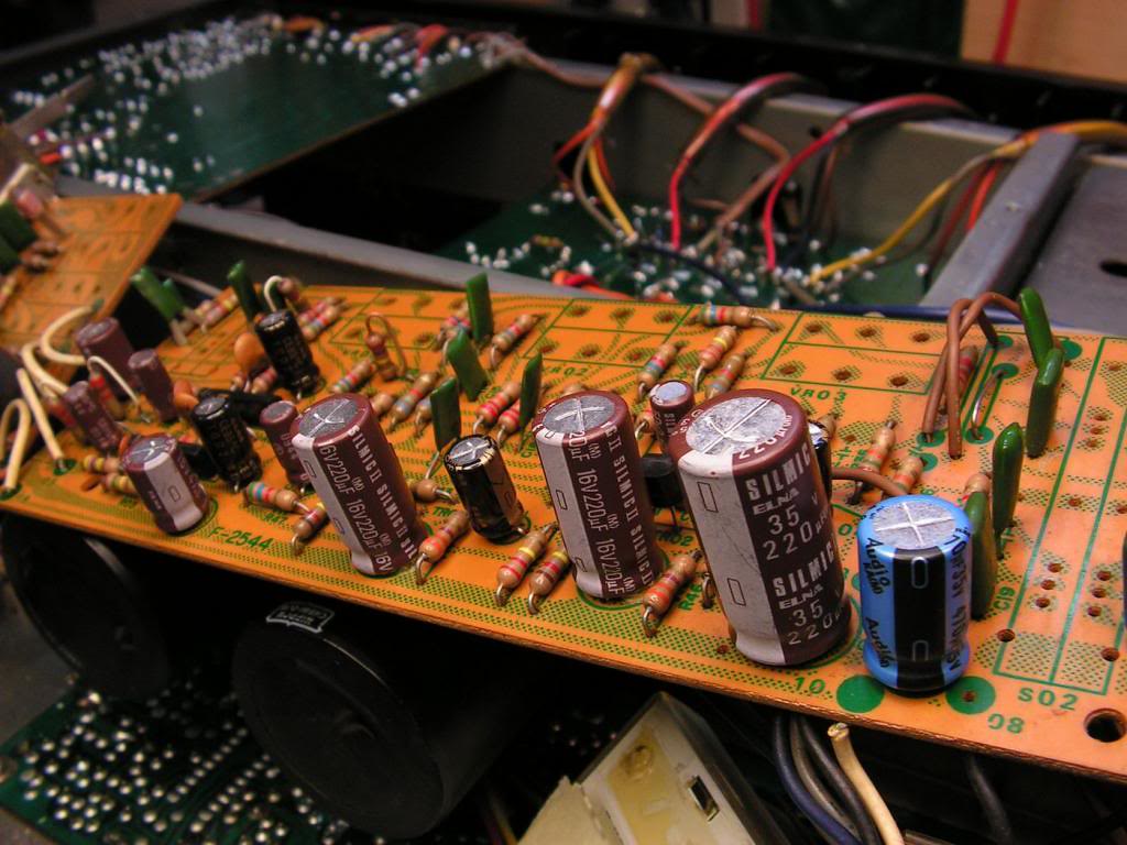
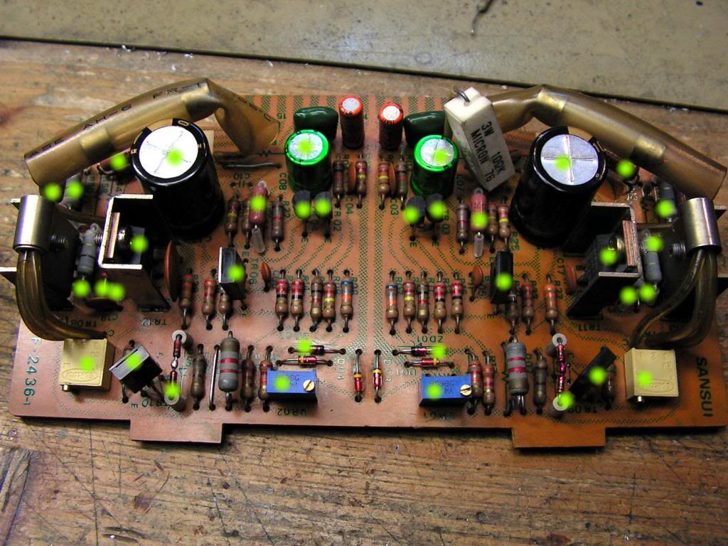
… driver board…
After I resoldered all solder points…
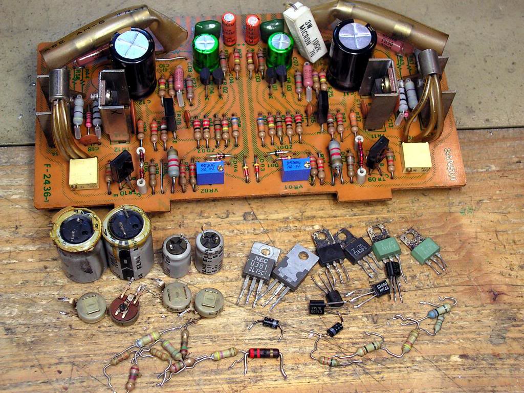
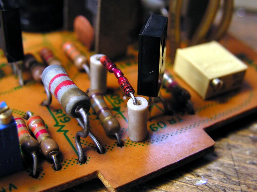
What I have changed on the driver board…
Some details…
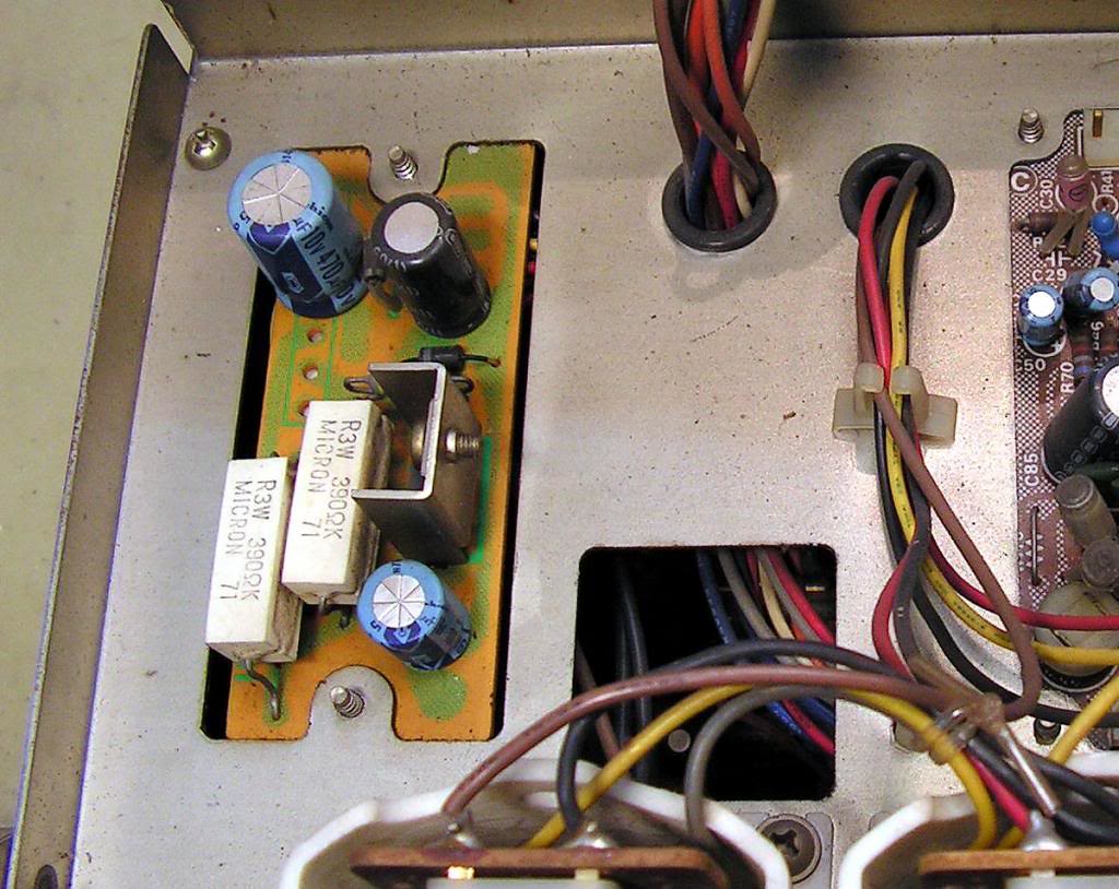
Just one step until end… Tuner Power Supply Board
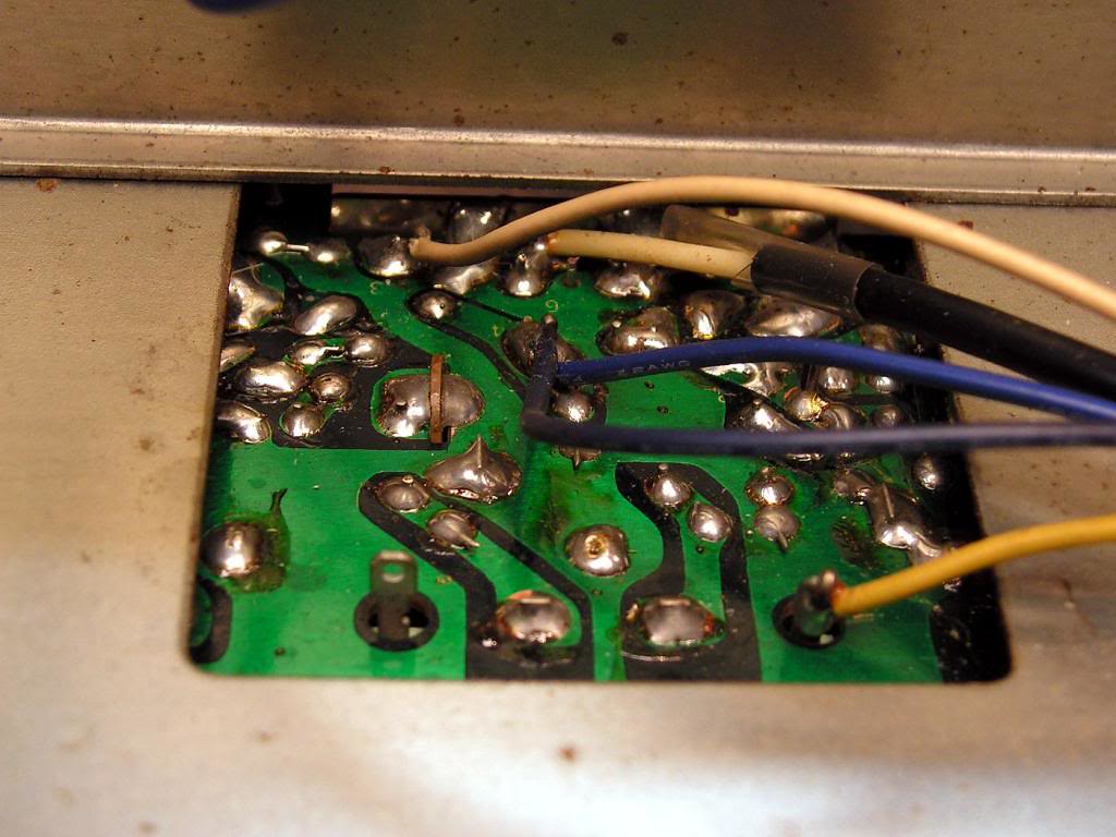
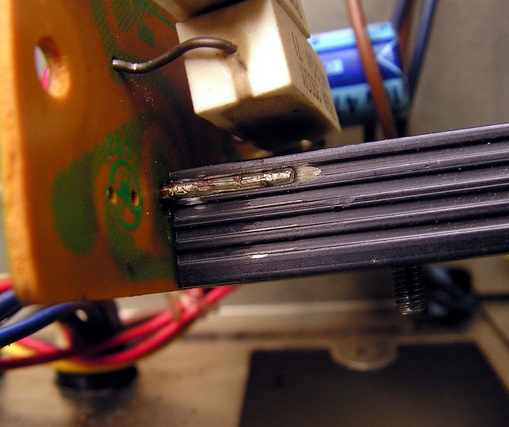
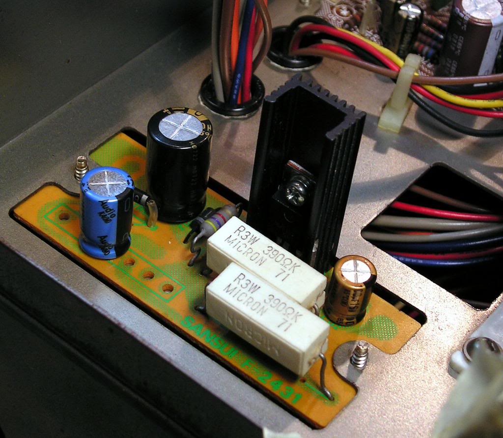
There, I changed an original heat sink with better black aluminum heat sink, because that TO220 transistor generate heat, and I think that new one is much better than old…. But I had to adapt it to holes for fixing heat sink to the board…
Finally it looks like on picture below…
Almost finished… installed back power TO3 transistors…
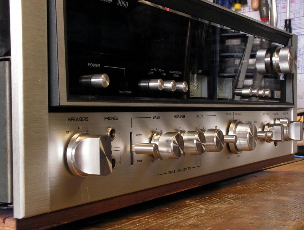
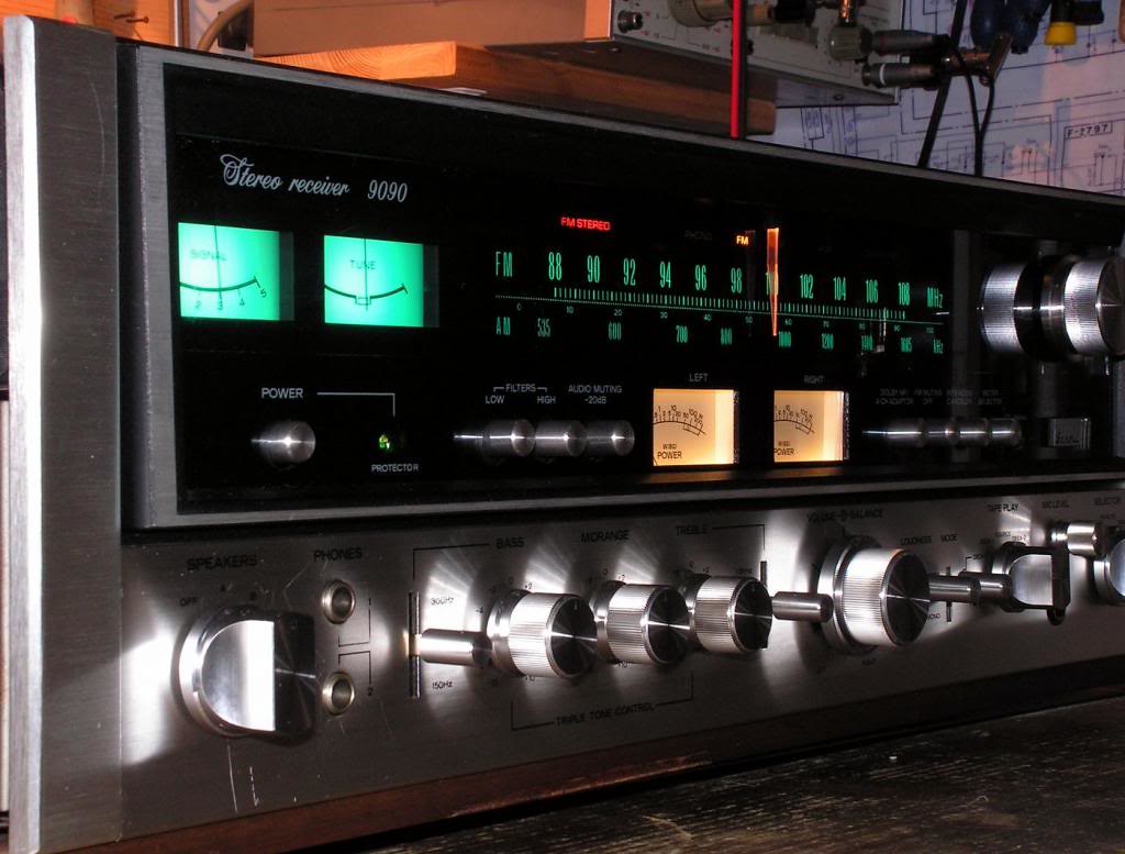
And at The End… The final pictures
