Again one very interesting Sansui restoration, I am going to show you all restoration process. I have so many pictures from that job…
That amplifier I have bought in Japan directly, and it was for 100 V AC only. Because of that I asked the seller of that unit to remove main transformer, just only to reduce amplifier weight.
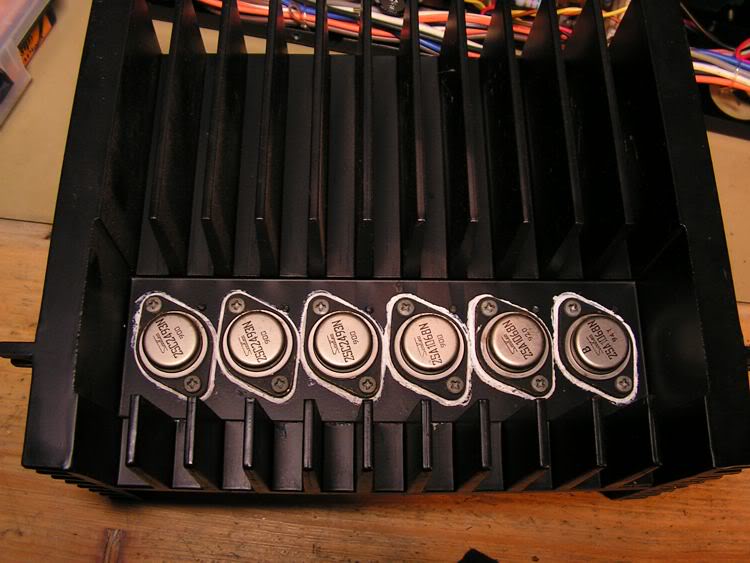
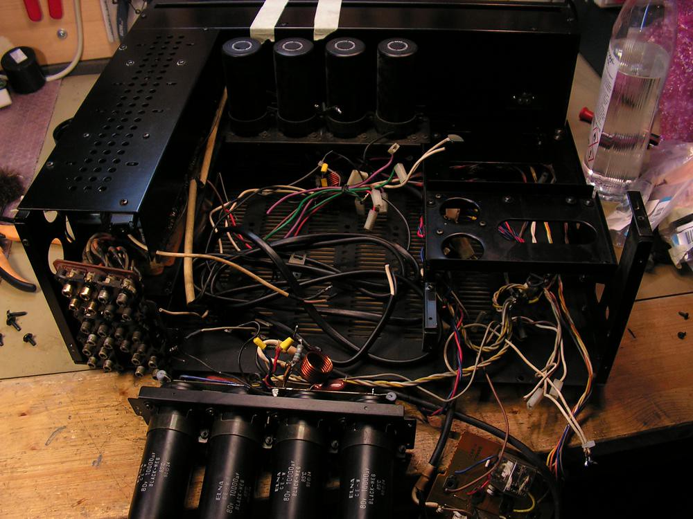
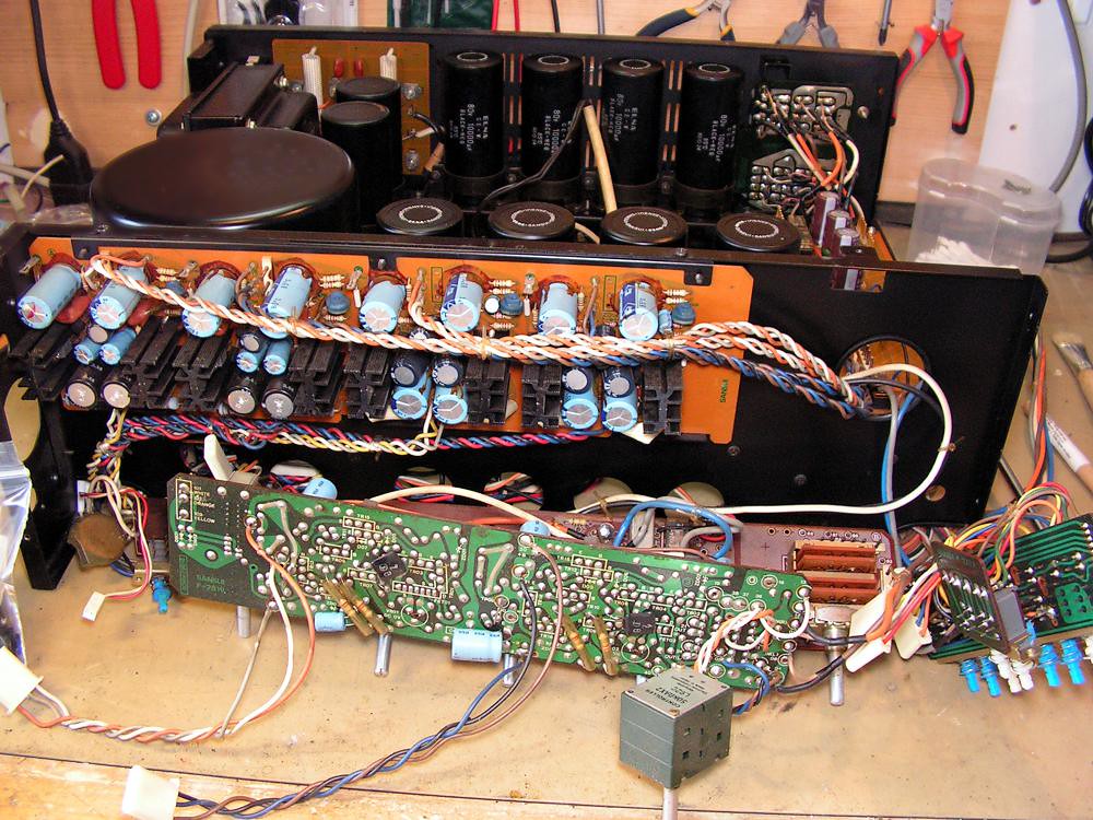
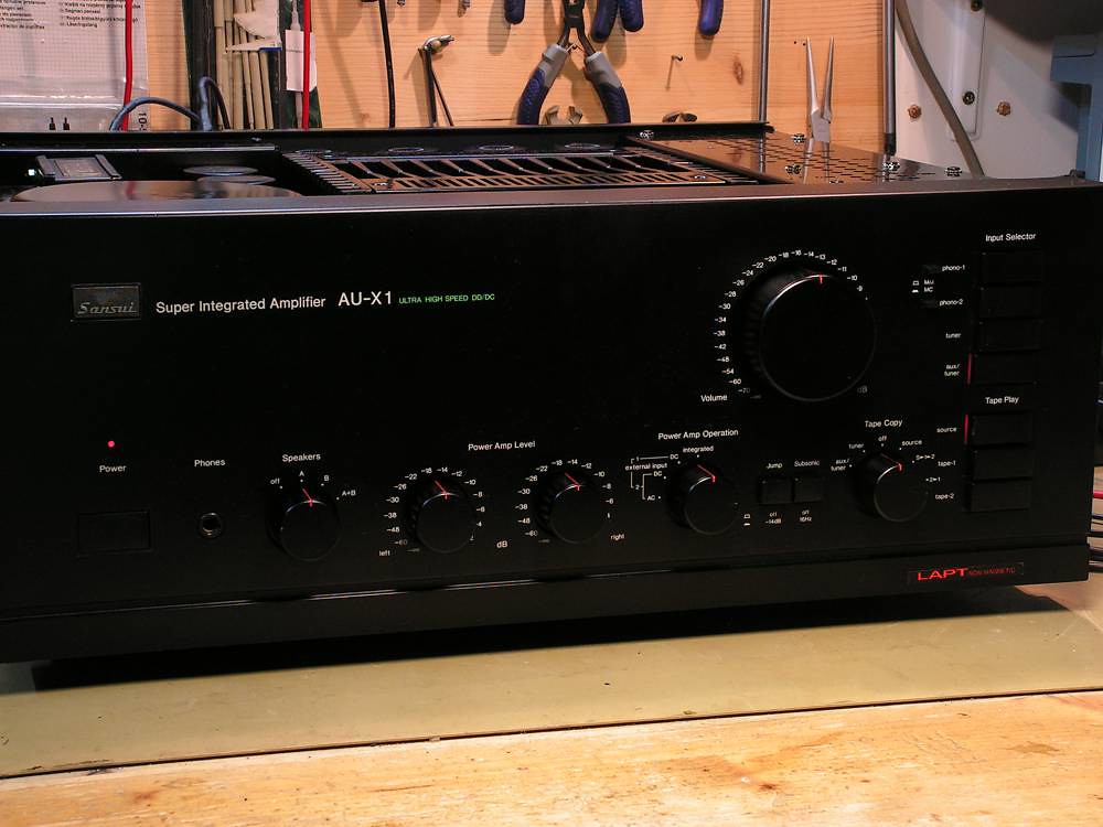
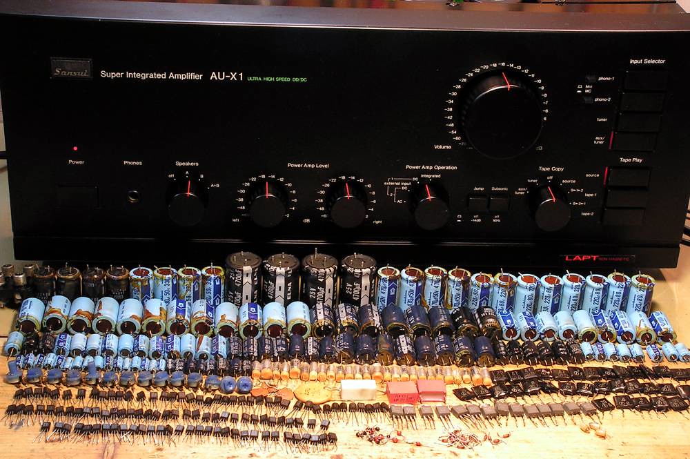
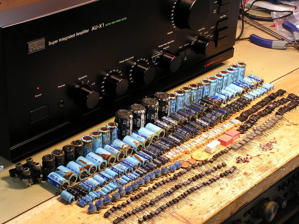
And here it is… on my bench
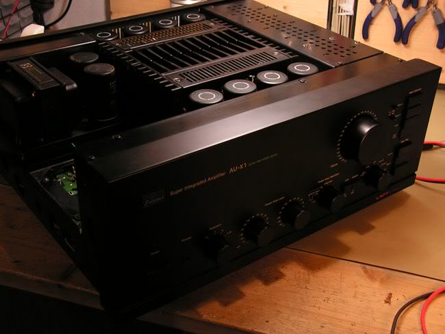
As you can see it is very clean on the outside, and it is in the very good condition on the inside as well
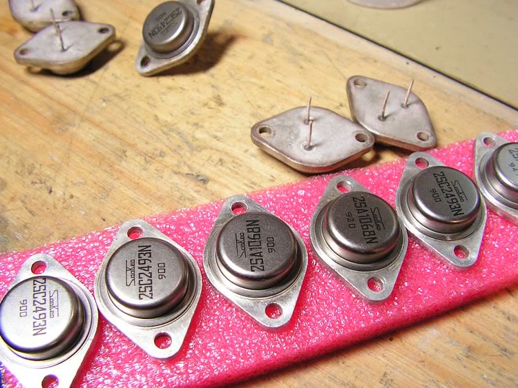
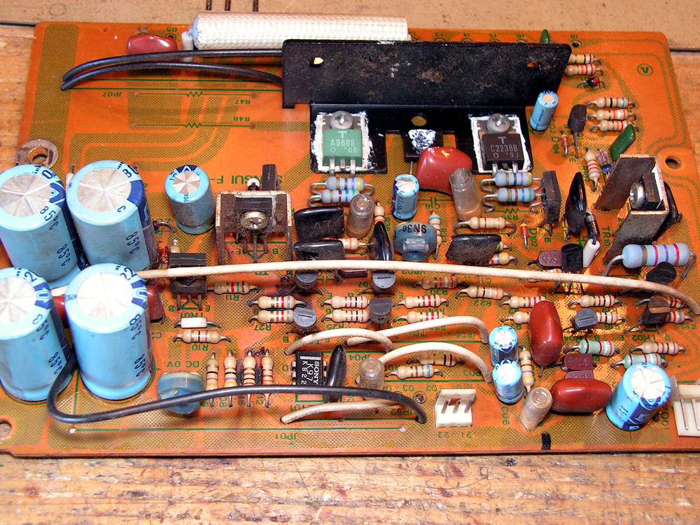
And the most important to me, it has genuine Sansui (made by Sanken) TO3 output transistors
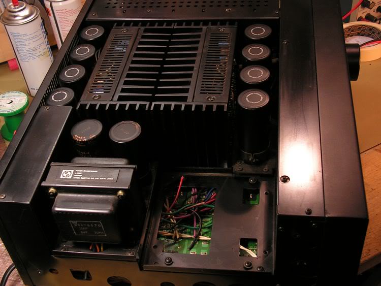
Main transformer
So the next task was to find one genuine Sansui multivoltage transformer, and I have found one,
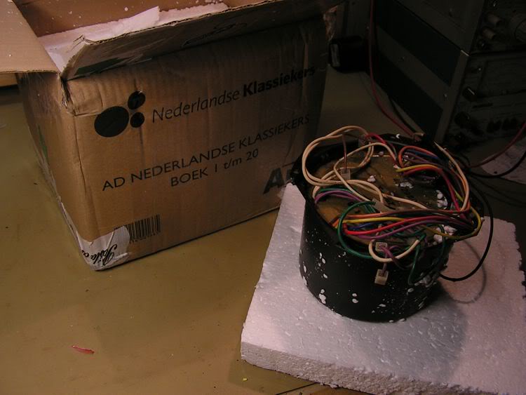
Unfortunately, that was not good… it had shorted primary winding, so after so many days, I have found an another one and that was good!
So the restoration can be started!
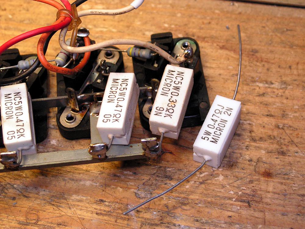
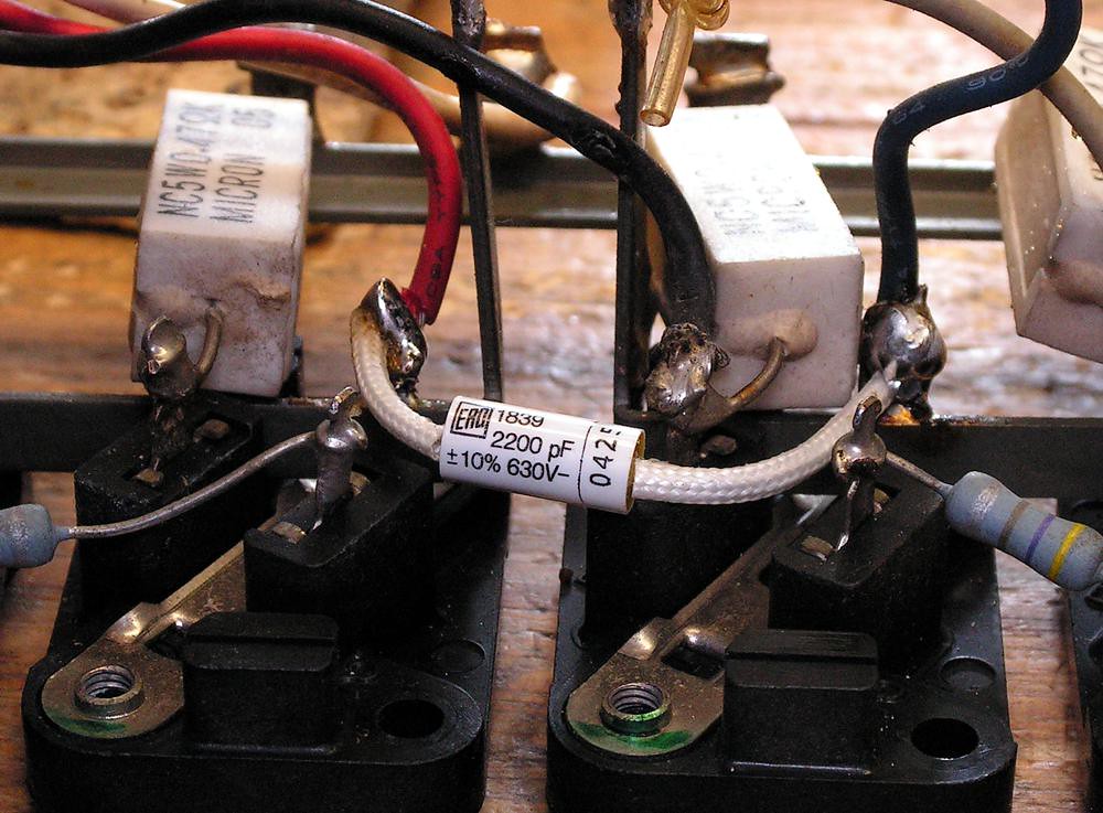
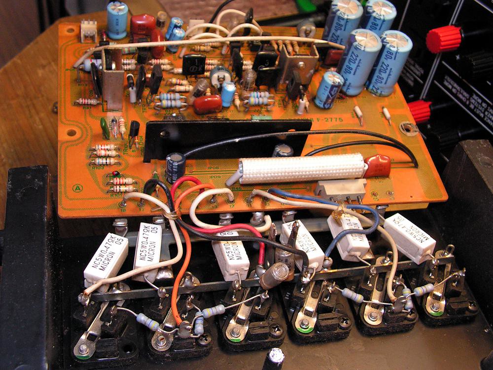
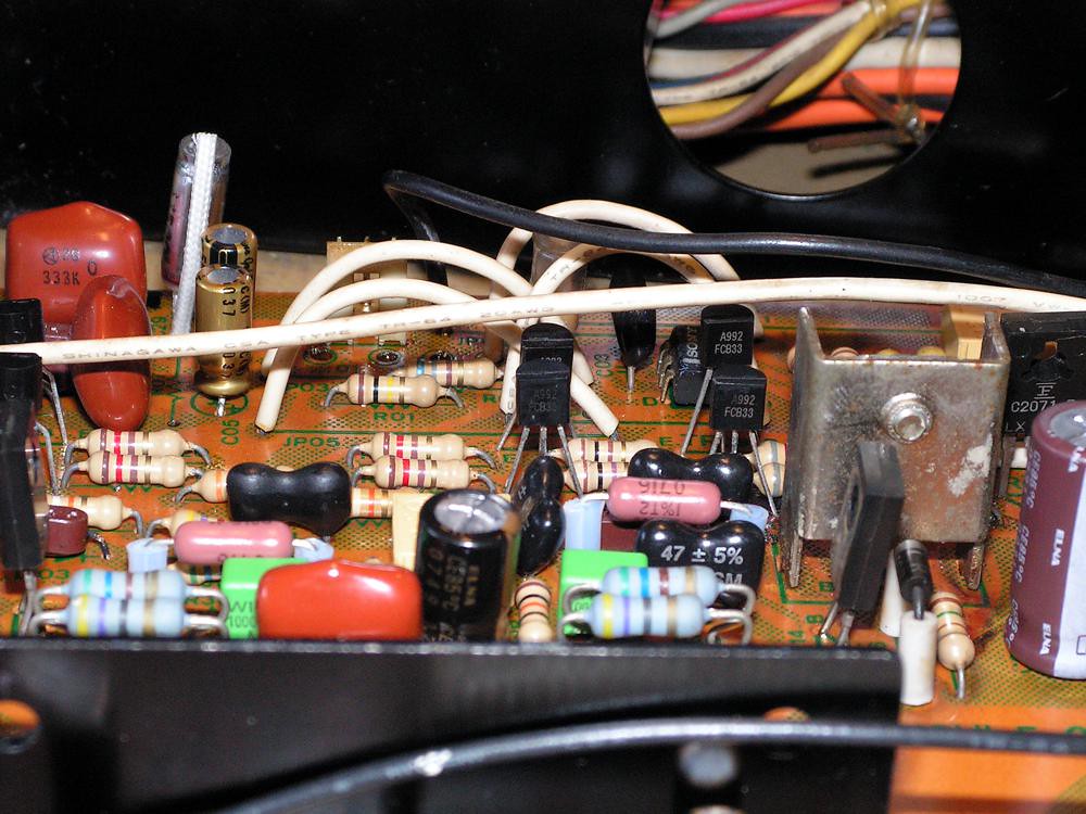
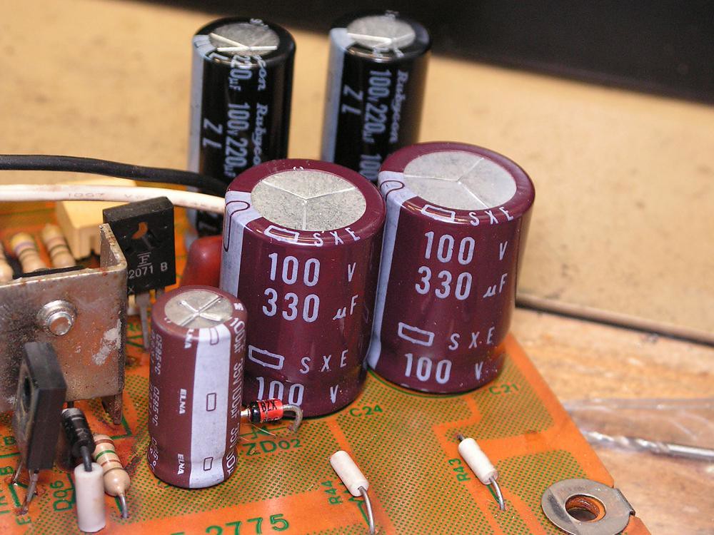
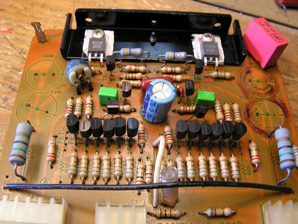
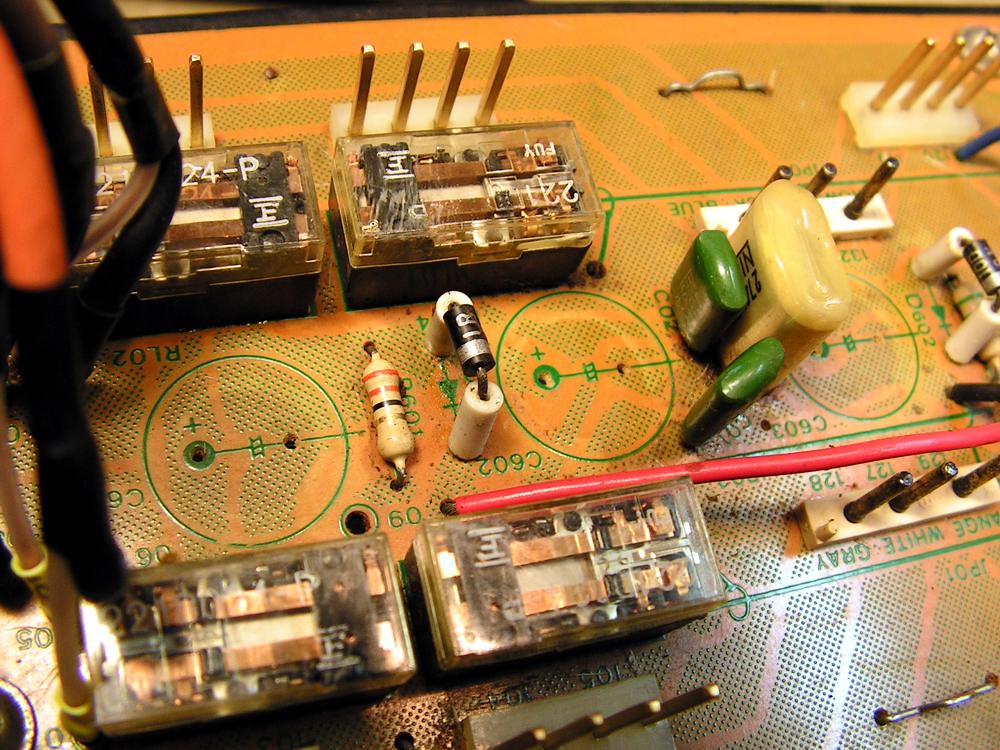
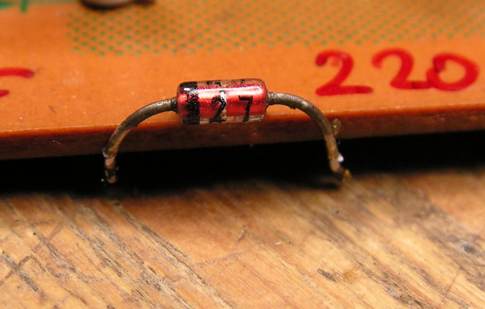
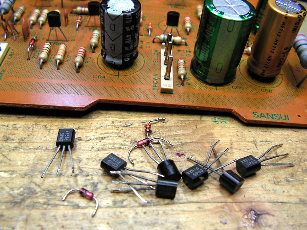
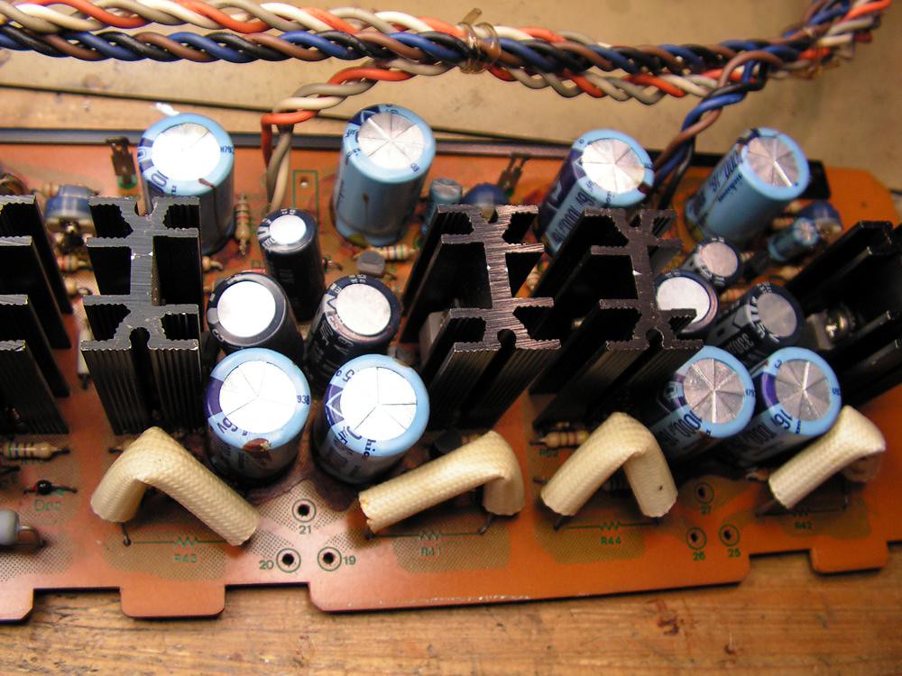
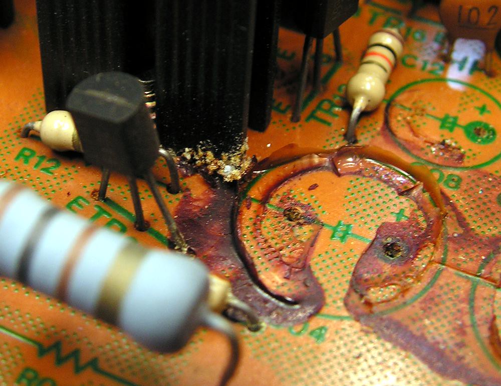
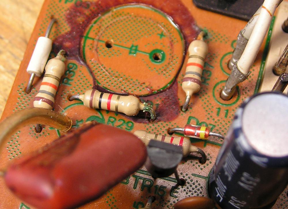
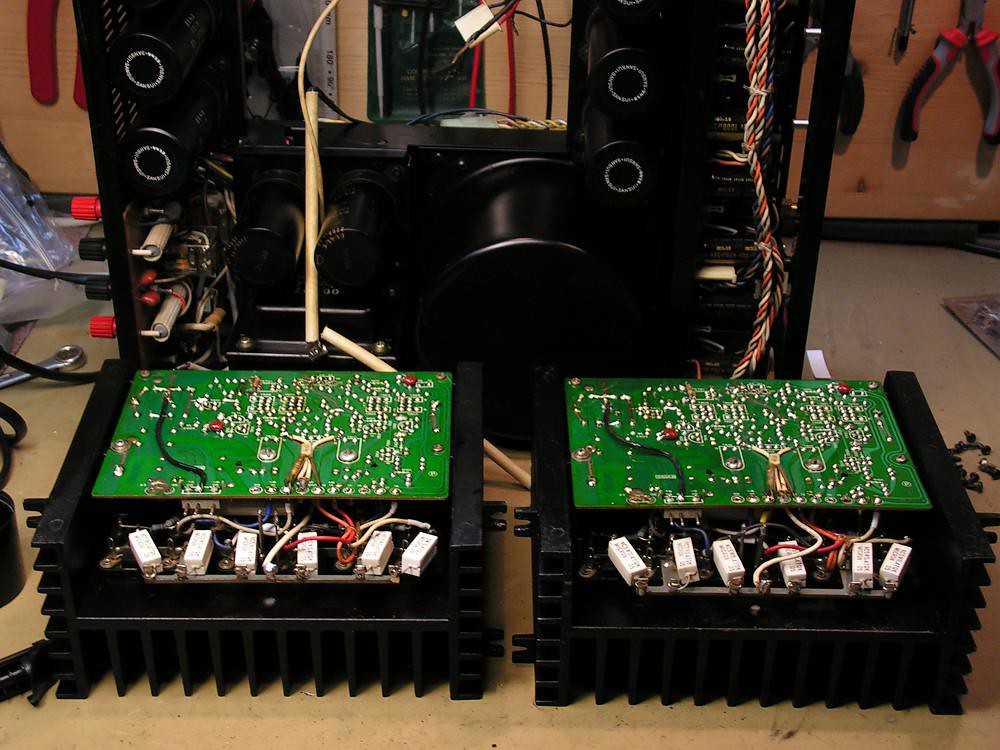
But first… please take a look at the next picture, and tell me what is strange on that picture ?
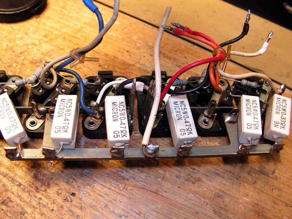
Yes! You're right! That 0.33 ohm emitter resistor there is installed by mistake in the factory!!! And what is really strange at Service Manual all emitter resistors are 0.33 ohm ?!?!
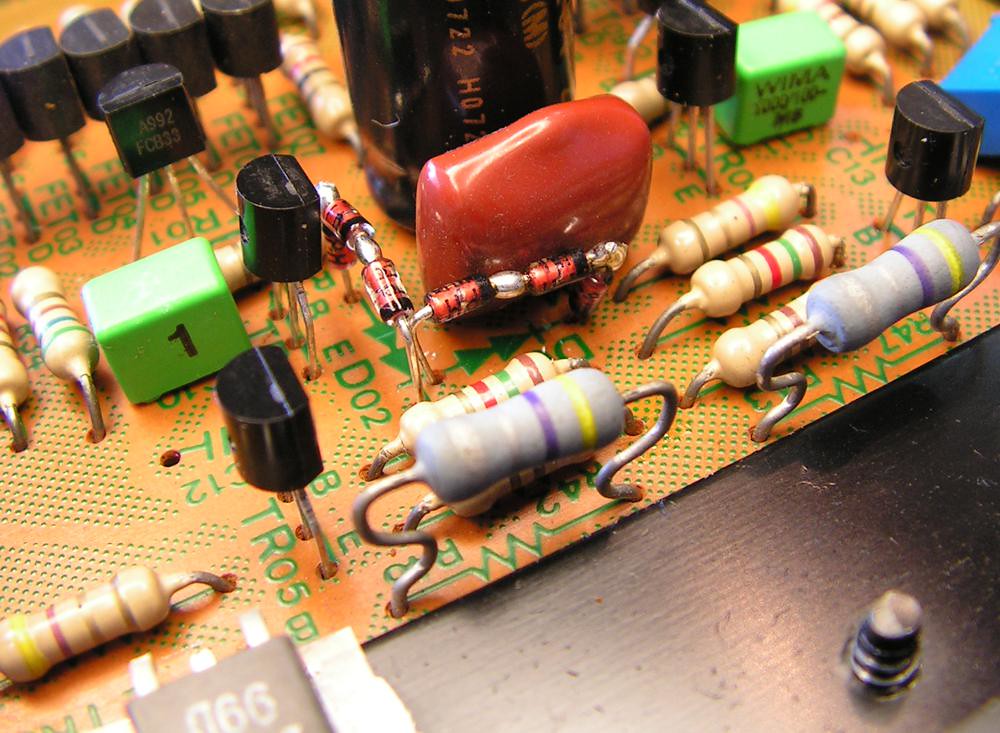
So I have to fix that… and what is good, I have an original NOS Micron 0.47 ohm 5W resistor…
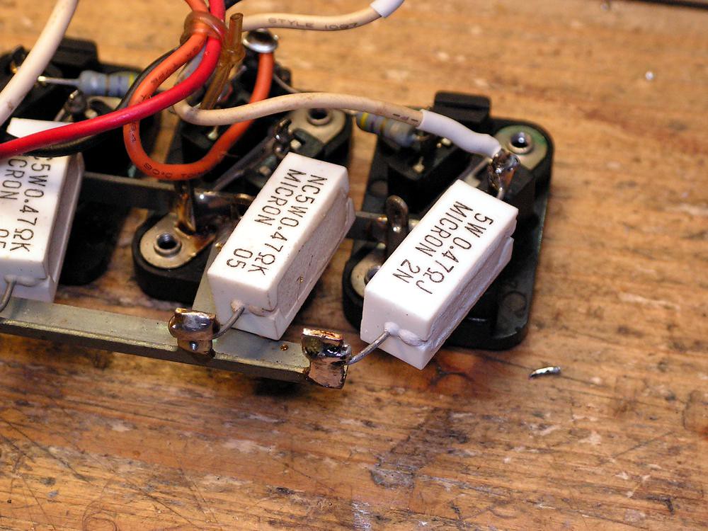
and the result is here
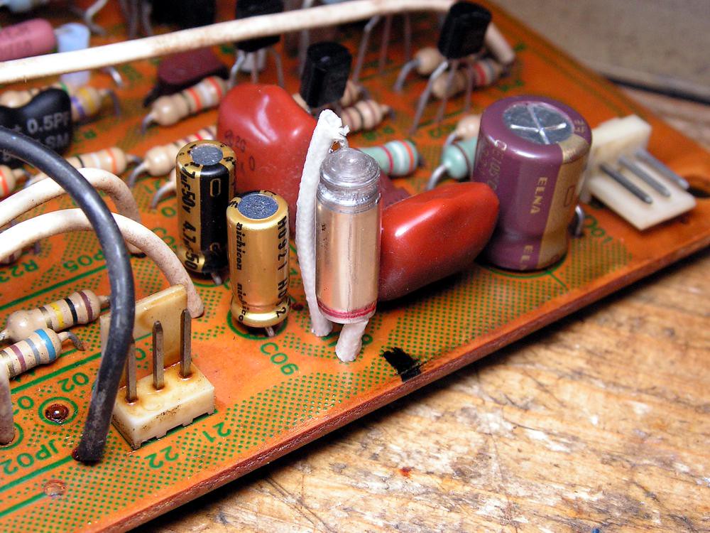
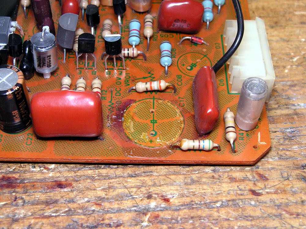
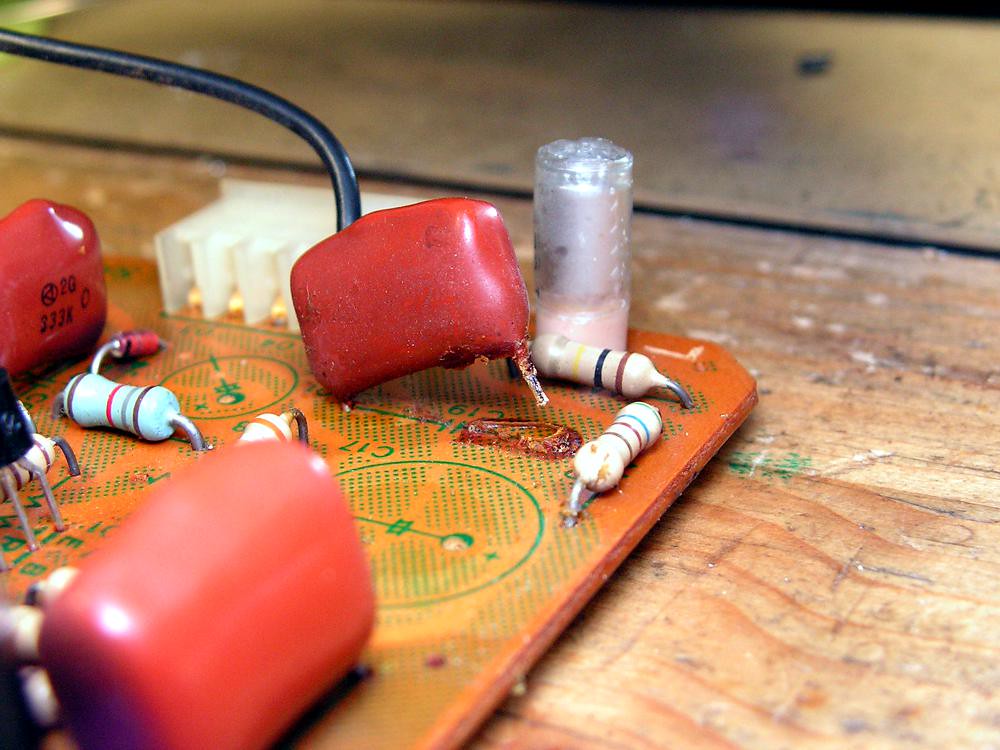
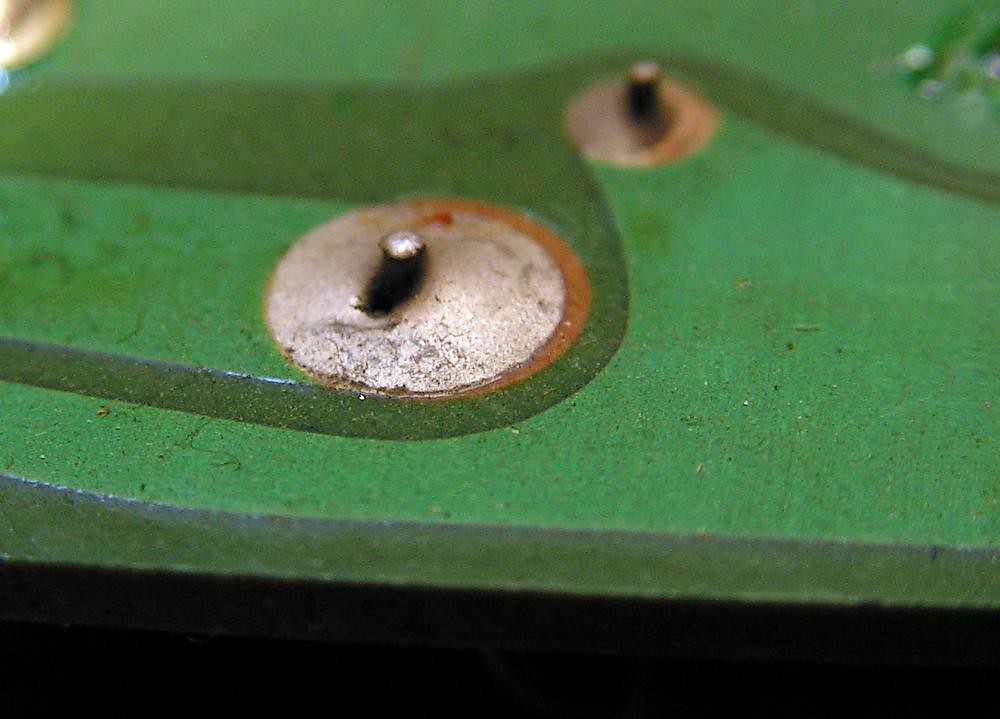
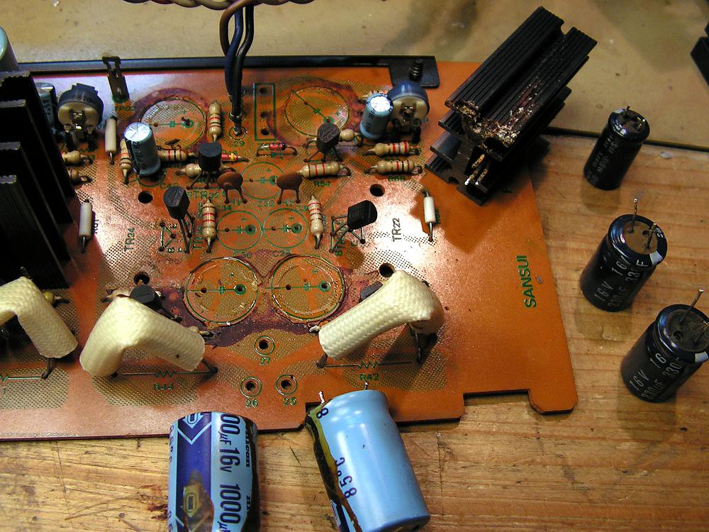
But that was not only one problem here… here it is another one…
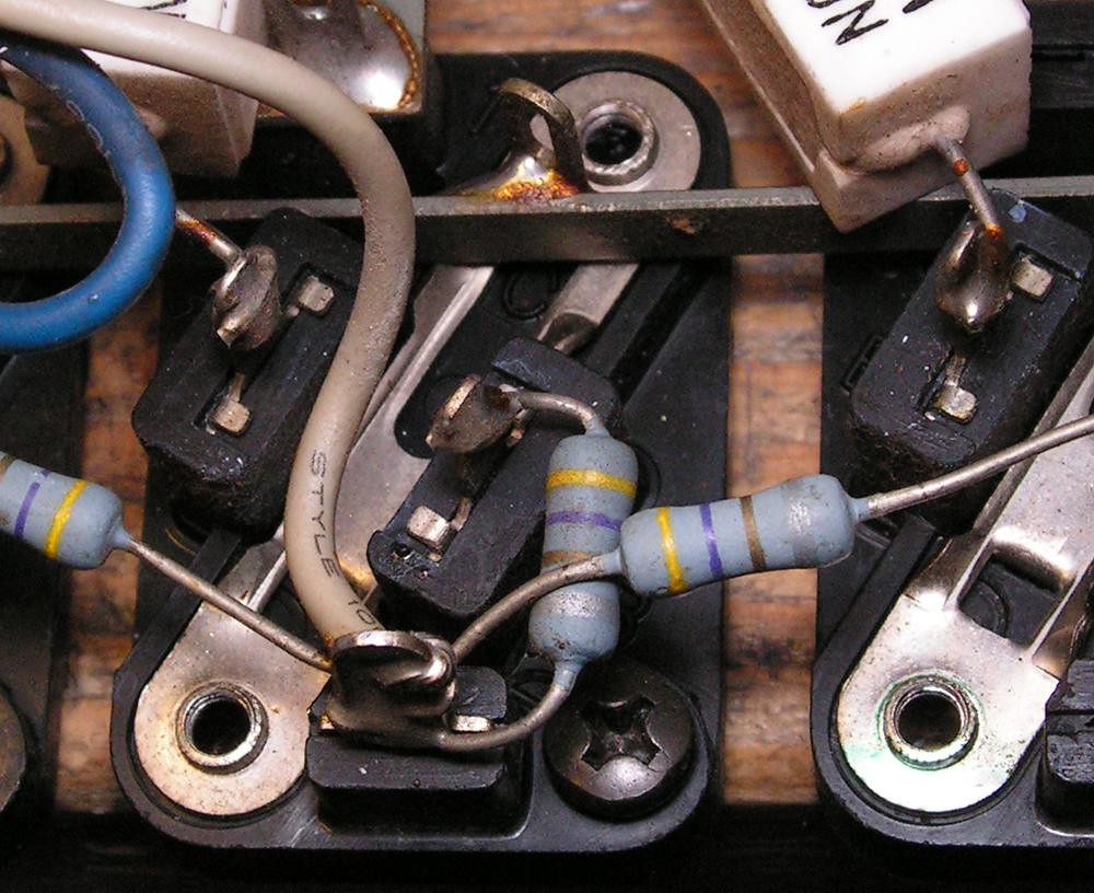
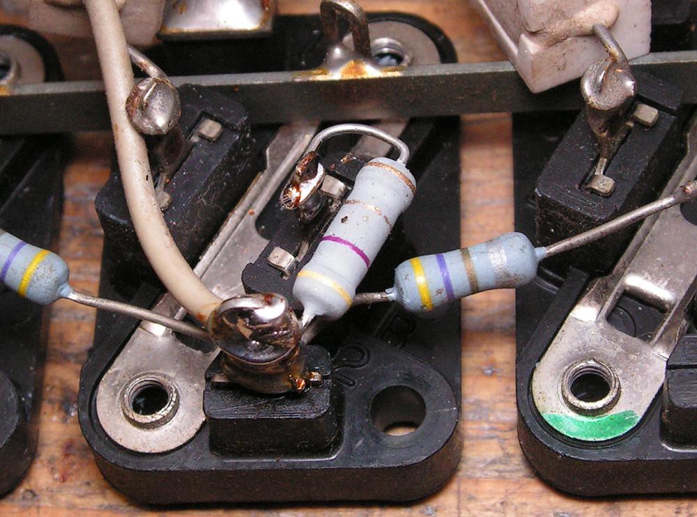
That base 4.7 ohm resistor is so close to that screw, and it is really hard to unscrew it without damage that resistor, so I changed it on that way
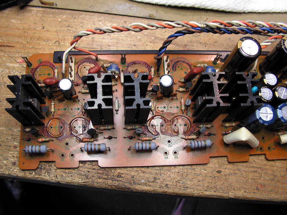
So the next step was to dismount the amplifier…
I have changed the styroflex capacitors between plus and minus output stage power supply with polypropylene capacitor
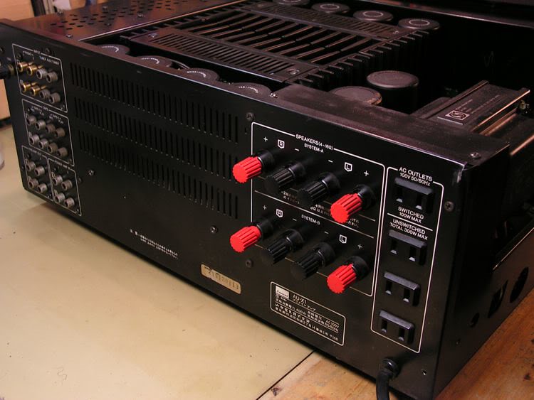
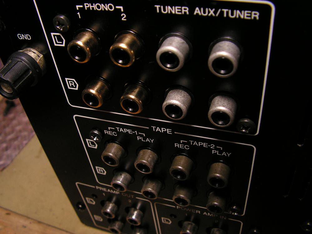
RCA Connectors
Here I wish to say that really I can’t understand why Sansui installed those RCA connector which are corrosion very sensitive ??? Yes they are silver coated, but after all those years they don’t look so nice….
I have some of them NOS, so I changed those for AUX and Tuner input
Changing them is not some easy job, because you need to be very careful
And the result is here
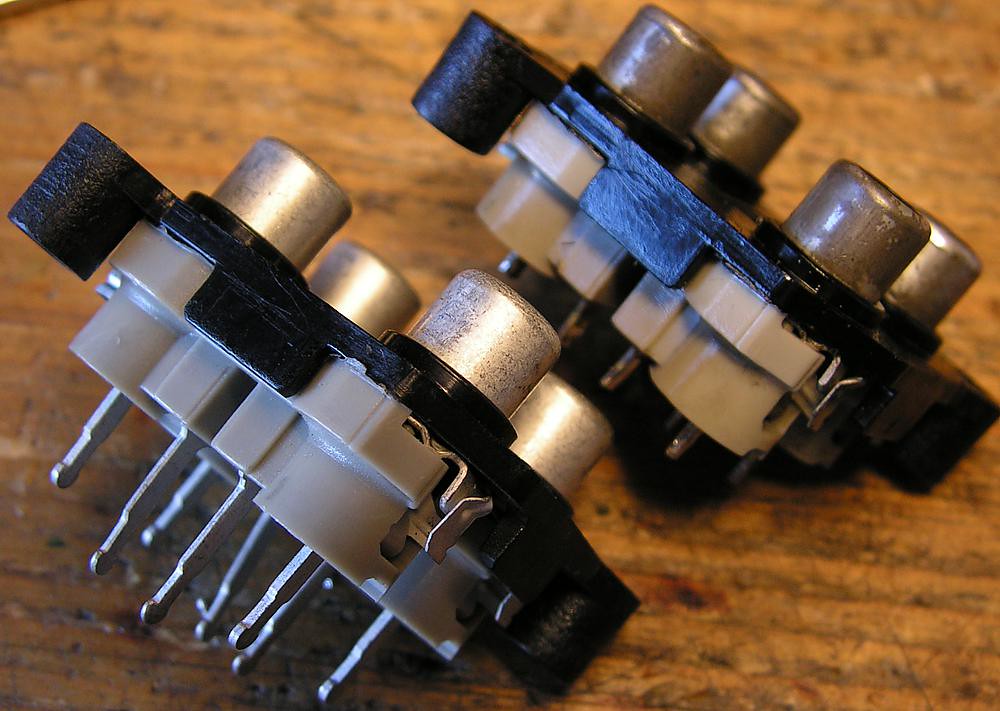
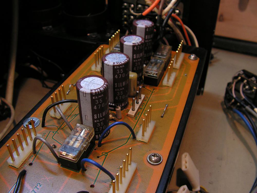
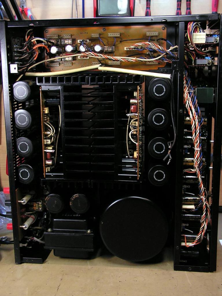
Dual Cap 2200uf 100V
The next step was restoration those Dual Caps made by Nichicon
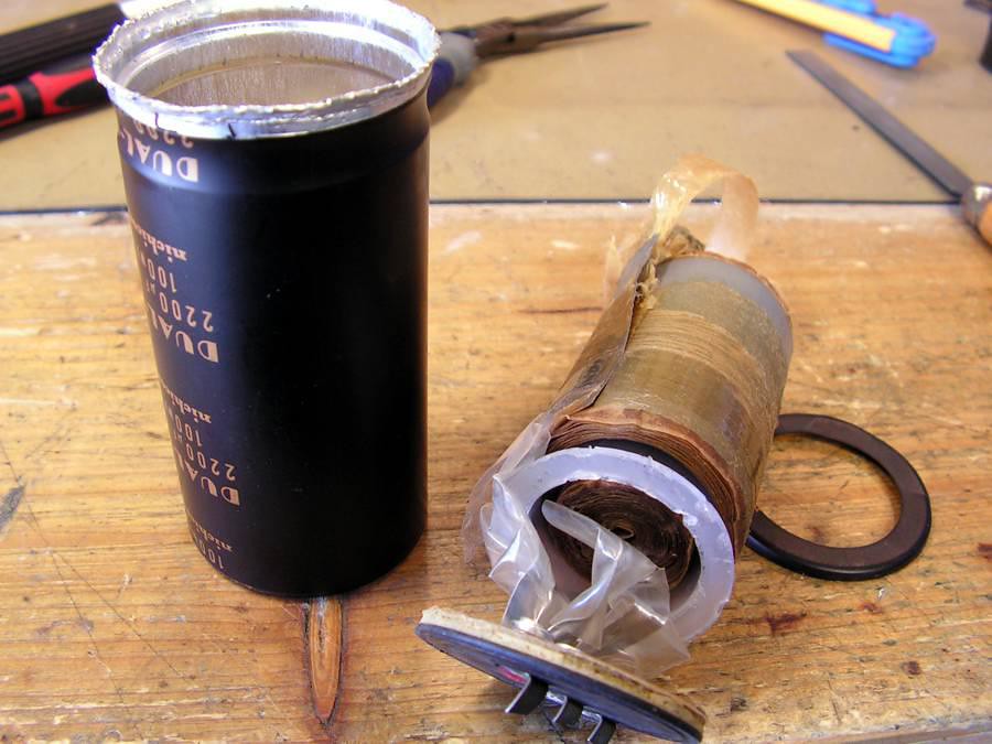
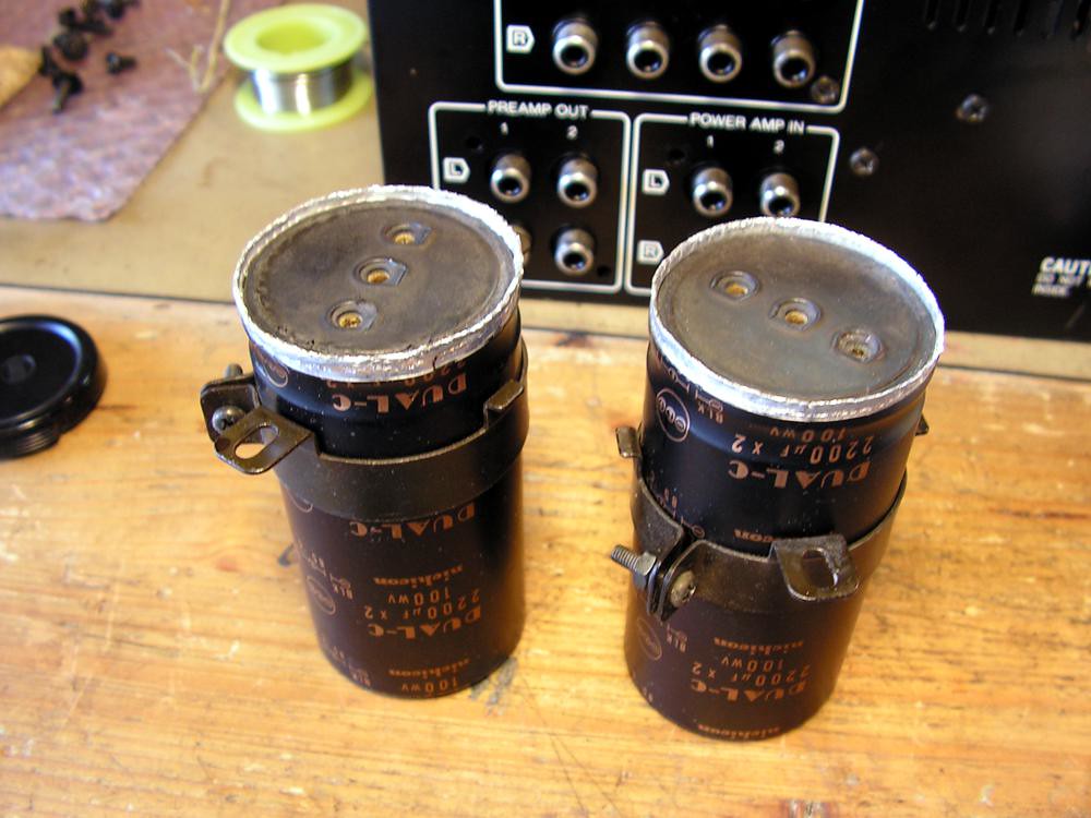
And the best capacitor for that was 2200uF 100V 105 C made by Kendeil
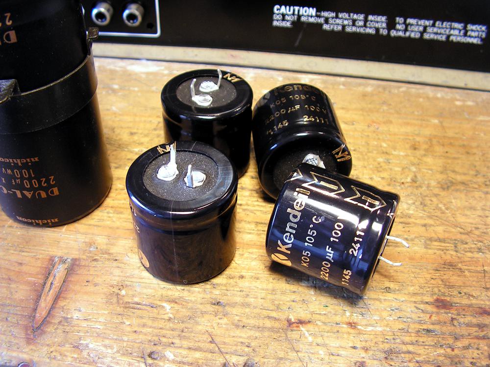
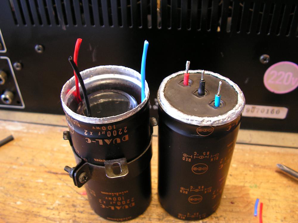
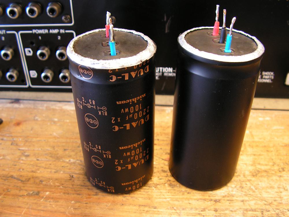
I covered the edge of capacitor case by heat-sink tubing
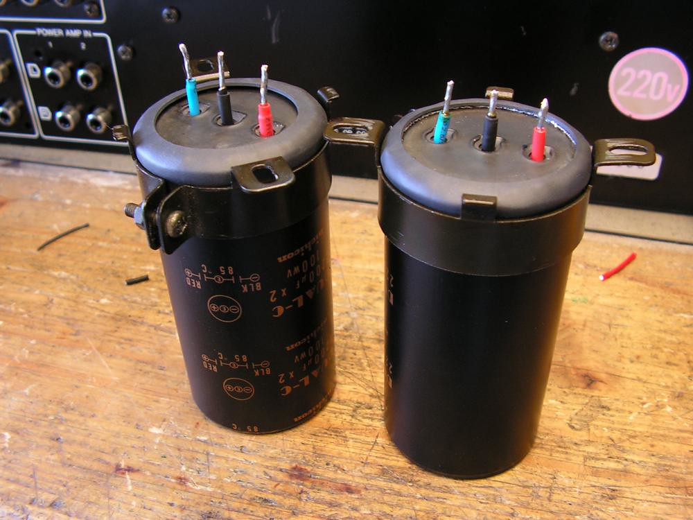
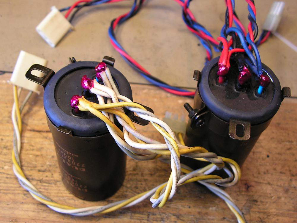
… and at the end, connected the wiring
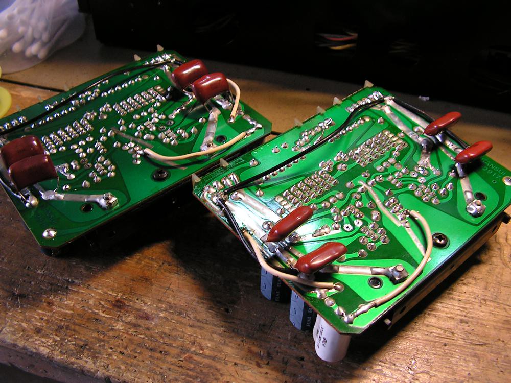
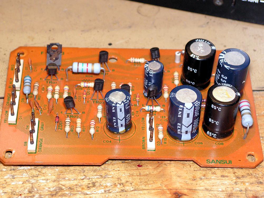
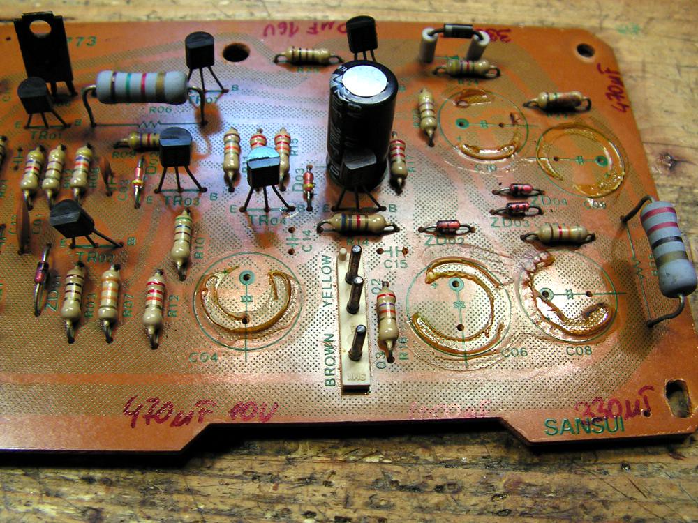
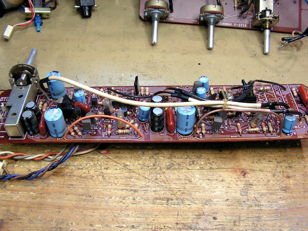
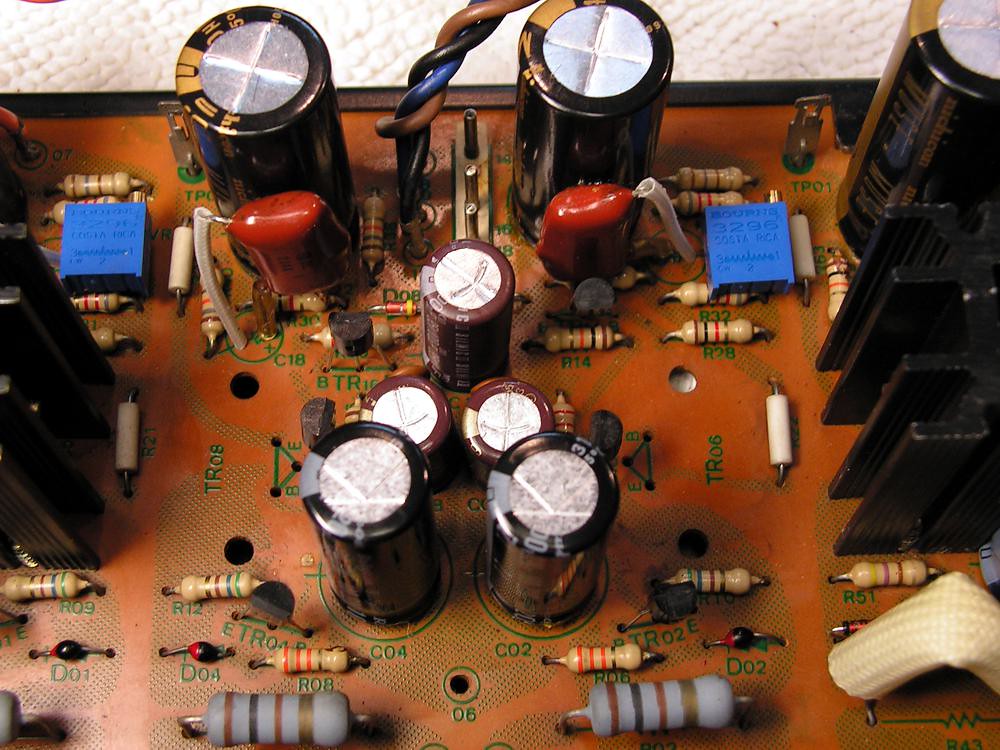
Driver Board
OK, now it is time to see what we can do on the driver boards
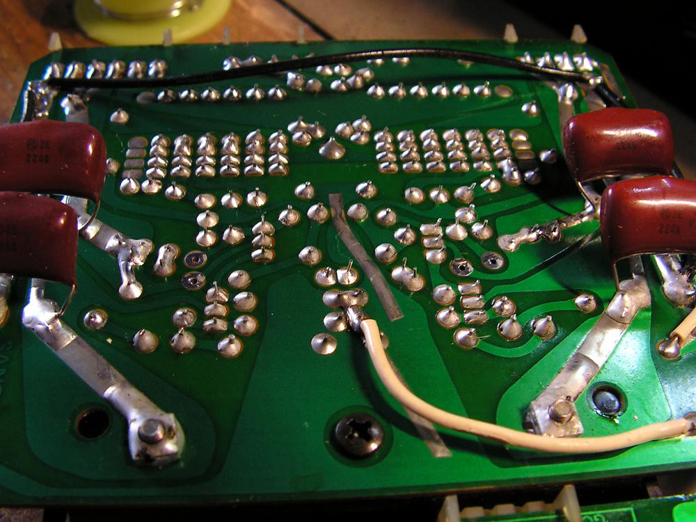
and here it is one detail what I have done on that board
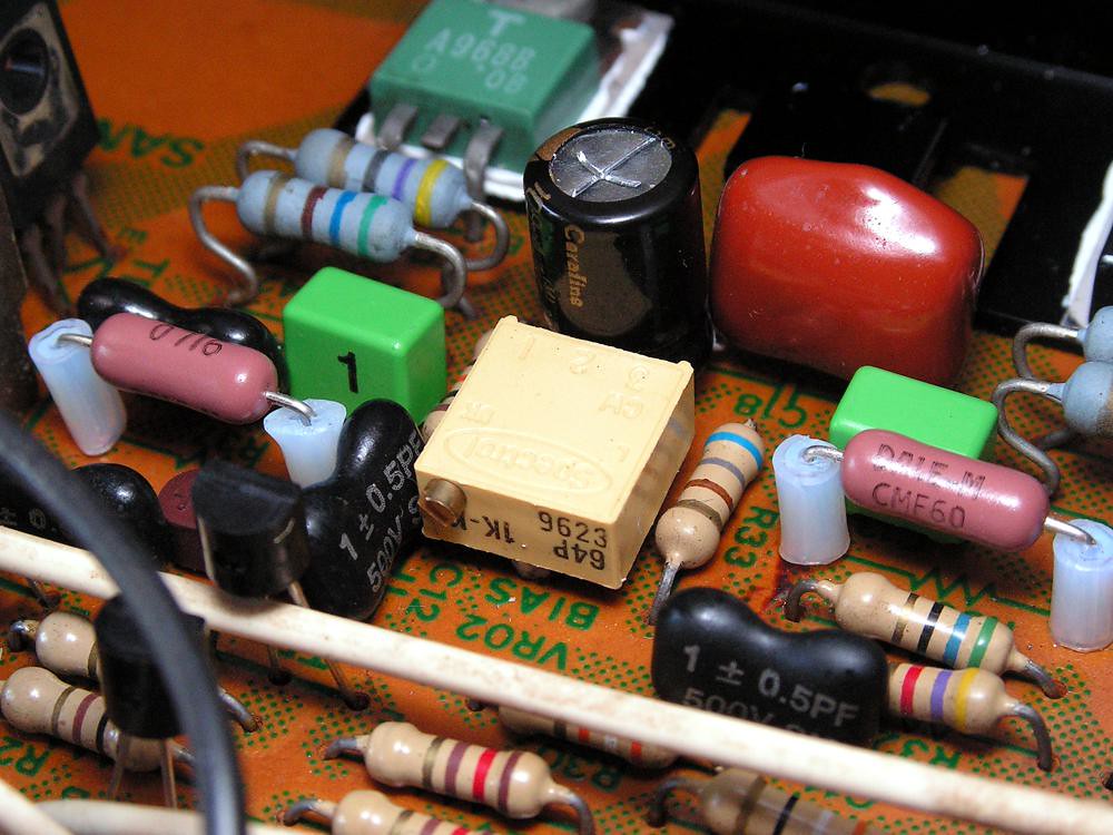
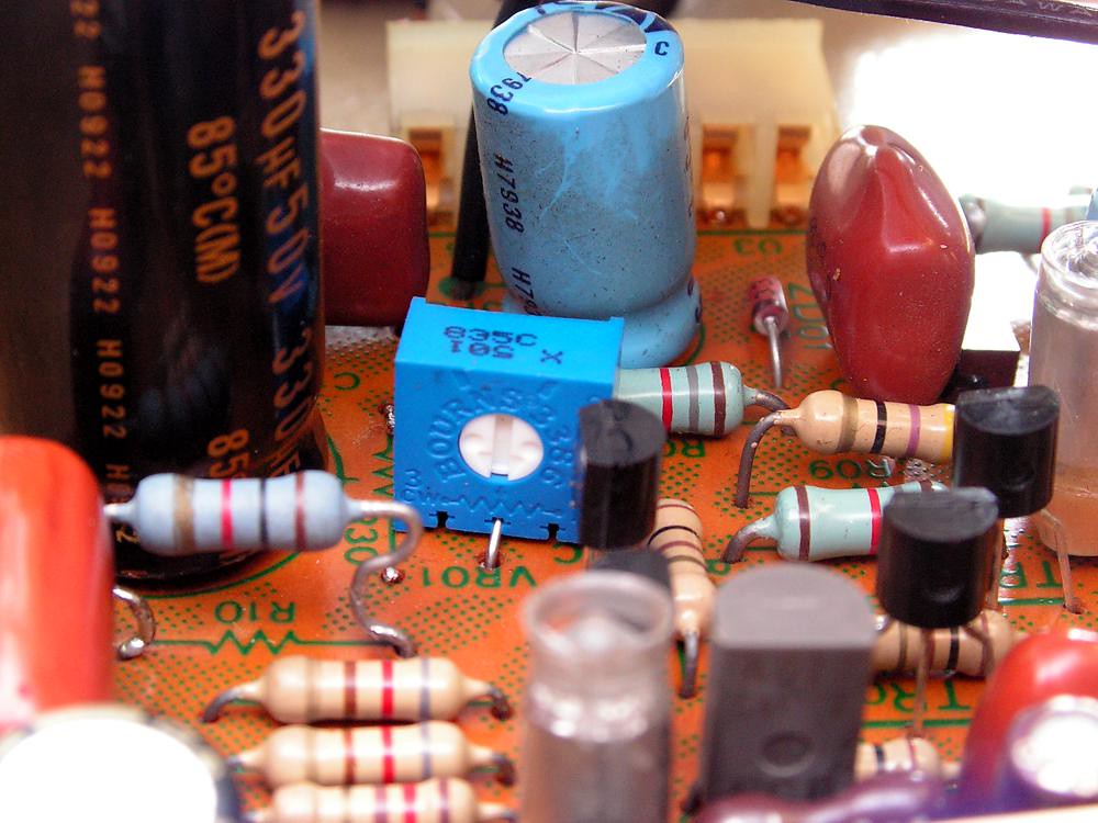
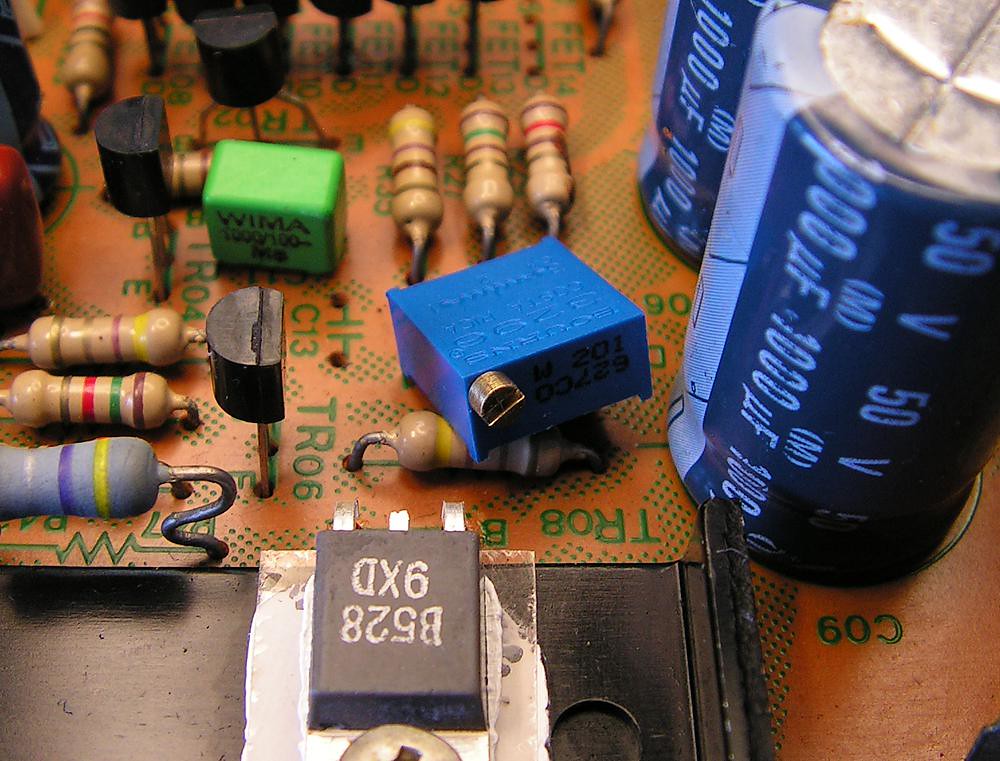
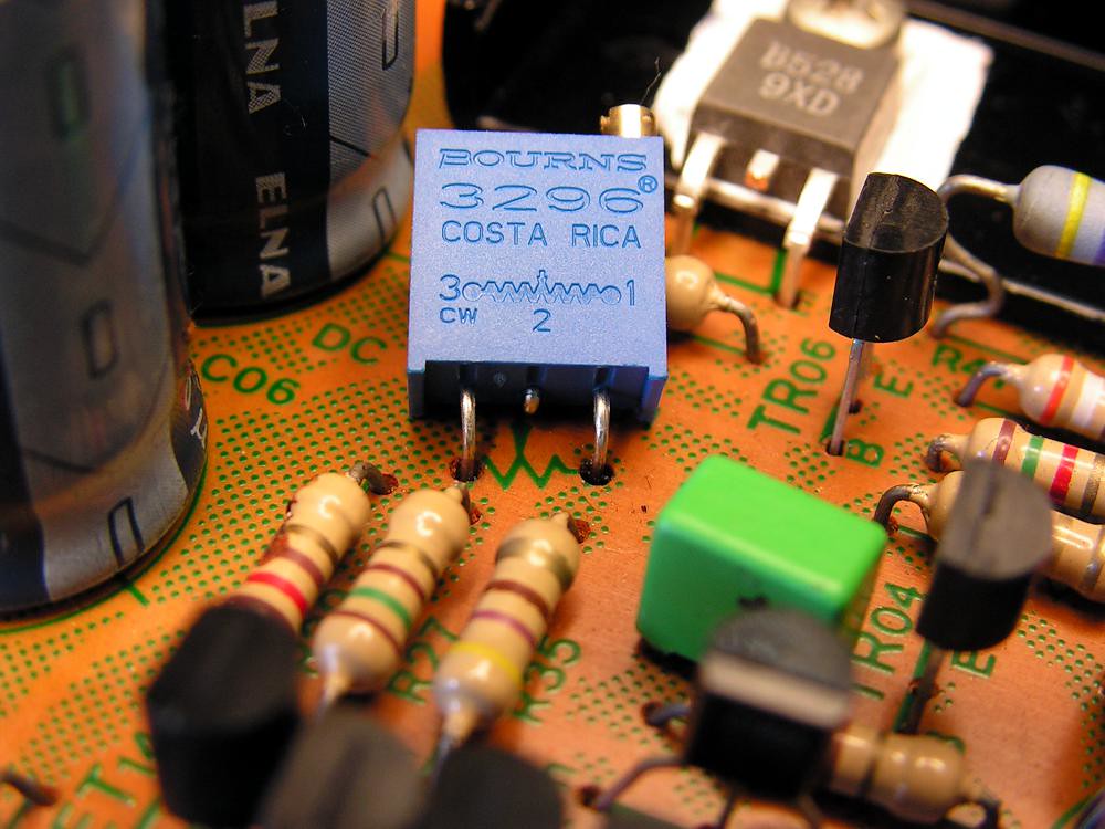
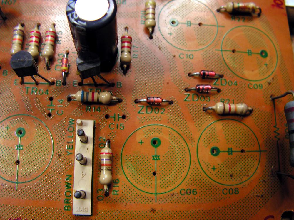
multiturn trimmer, vishay dale rn60 metal film resistor, Elna Cerafine, silver mica, Vishay polypropylene instead styroflex capacitor…
… deathly glue removed… zener changed…
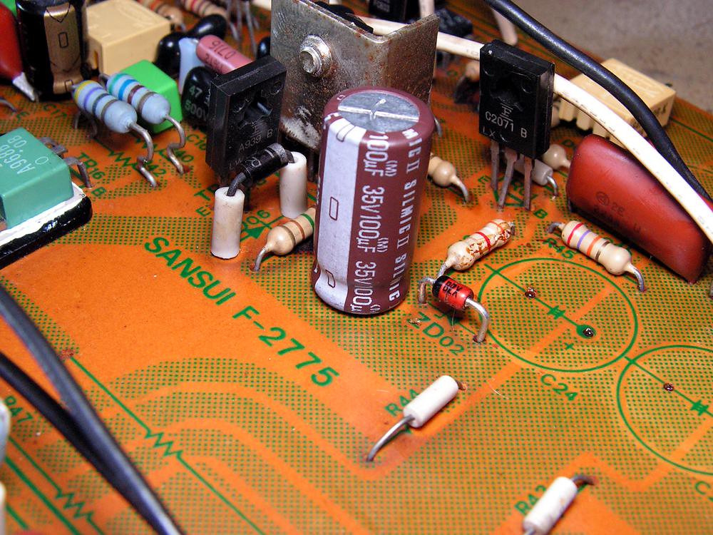
all small signal transistors replaced with the same model of today Fairchild Semiconductor production
replaced styroflex capacitor by the new one, but I didnt have radial type, so I installed axial type.
all solder points were resoldered, thermal grease replaced…
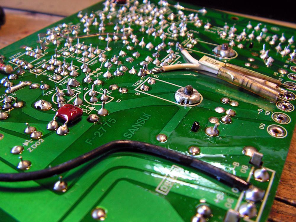
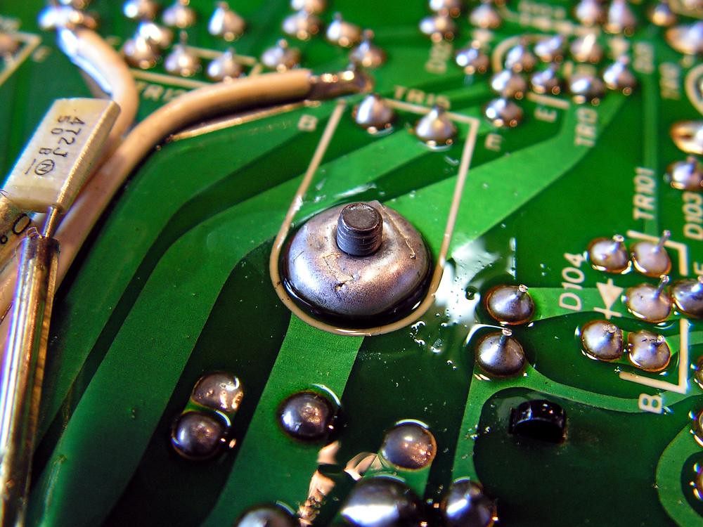
nut for fixing driver transistor soldered to the board for getting better connection (that nut connect collector of the transistor to the board)
On that driver board I made only one modification during that restoration; that board has four capacitors of 220uF at power supply circuit, but I decided to put close to power source two 330uF Nippon Chemicon (better filtration) and close to consumer circuit two 220uF Rubycon 220 ZL (speed).
All four capacitors are 105 degrees, because the board is located beside the heat sink.
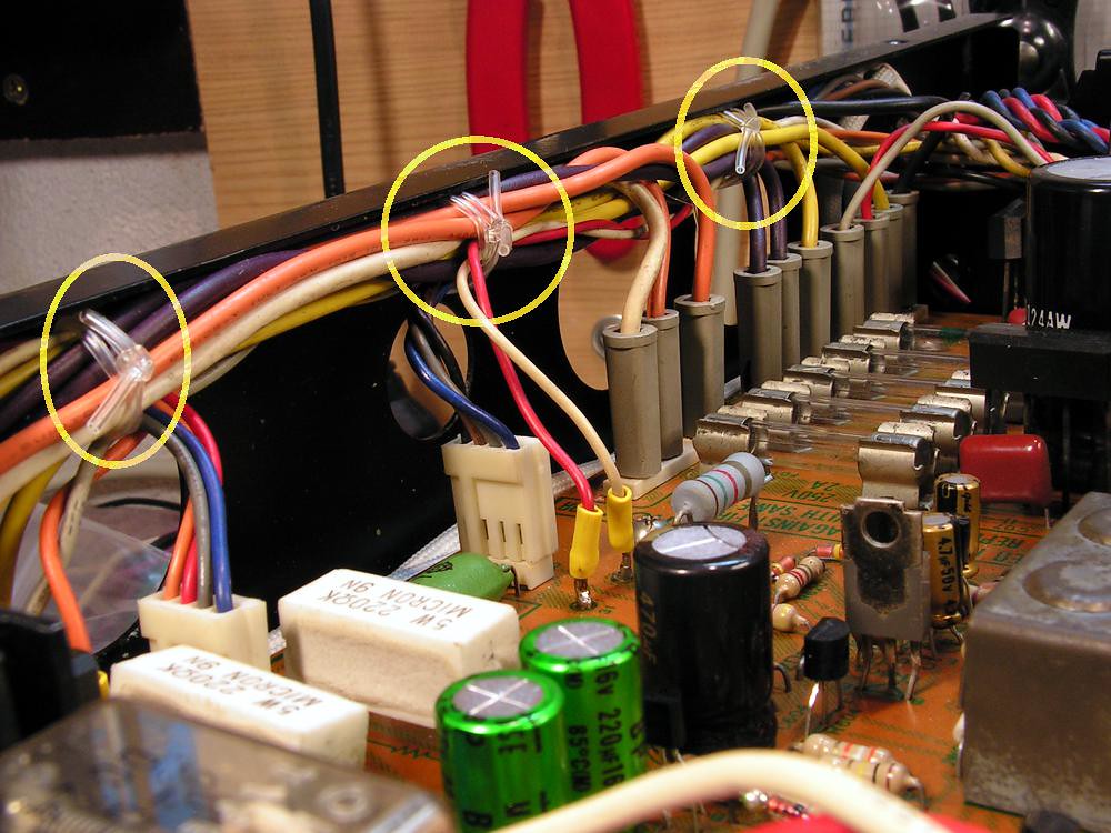
Finally, from that restoration I solved one big problem for me…
You probably already seen that Sansui fastened cables by some nylon tube, and I have searched all around the internet to find something similar, and finally I have found that
Now I am going to restore phono preamps (MM and MC)…
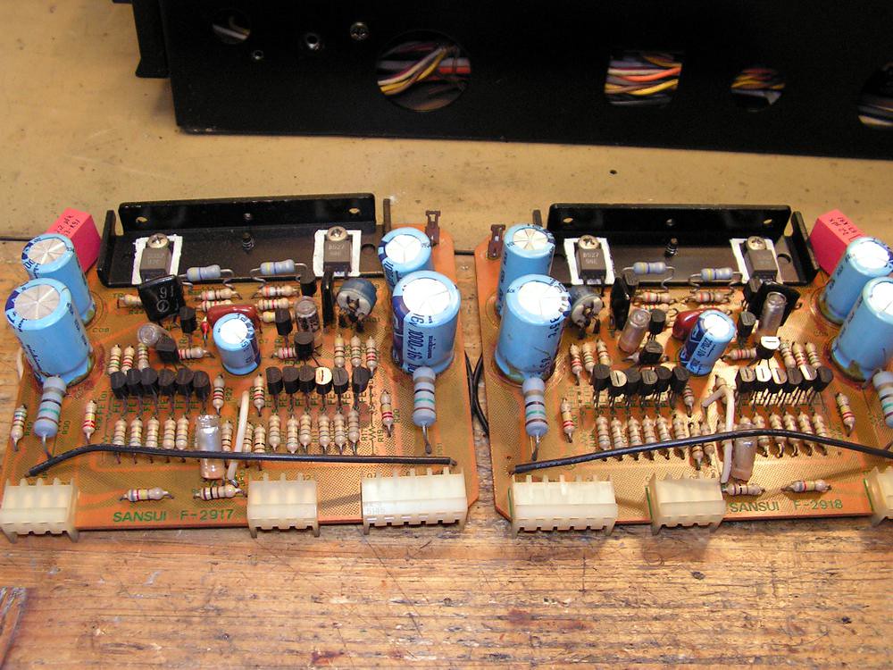
those pictures above are MC phono preamps-
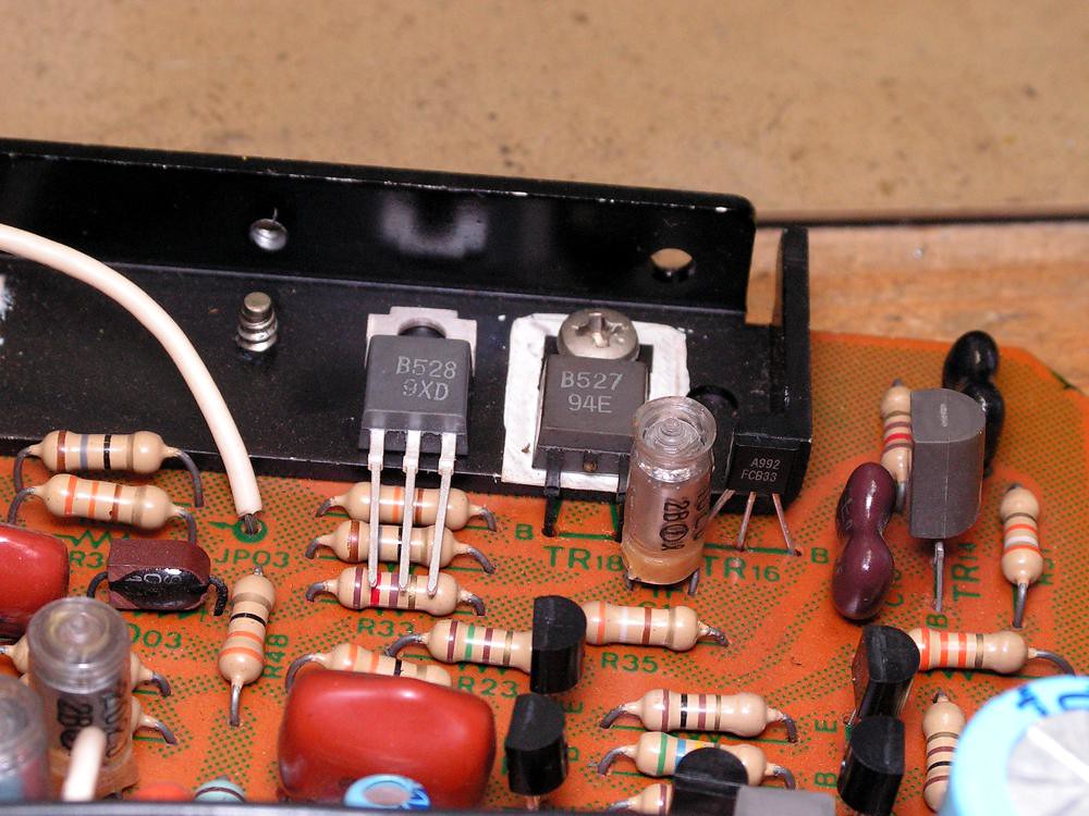
Because those preamps can produce some problems, I made a special attention to restore them… first of all I replaced 2SB527 2SD357 with 2SB528 2SD529 (greater Vcbo)
… then trimmers…
… on the left side deadly glue removed…
… again that glue… (on that picture you can see the new small signal transistors, there I have replaced them all)
…VD1212 replaced …
Those boards after I finished my restoration job…
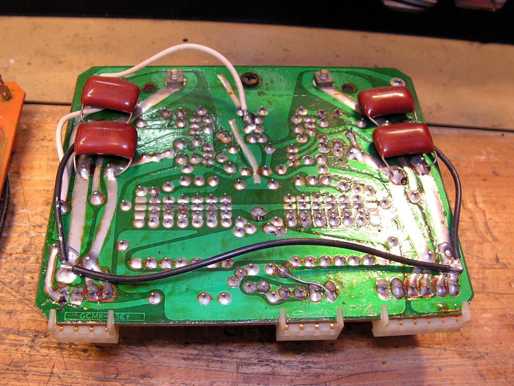
Motherboard for Phono Preamps
Now, the time has come to restore motherboard for phono preamp…
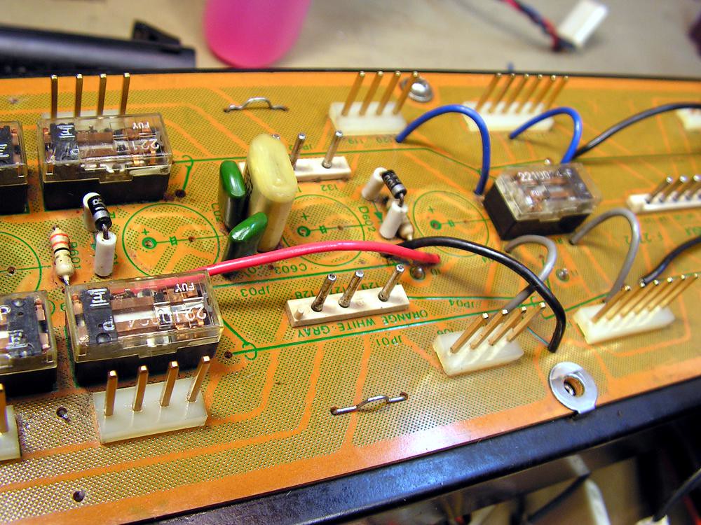
New capacitors installed
The Mute Board
Next was The Mute Board
One interesting detail
And now please take a look this picture
Those 500mW zeners are very small, and it is really hard to read marks on them, but on schematic diagram it should be 24V zener?!?! I decided to put a new one the same as the old was.
Again glue
… cleaned…
… replaced semiconductors …
… the result is…
Now the restoration work moved at the front of the amplifier…
There will be a lot of work….
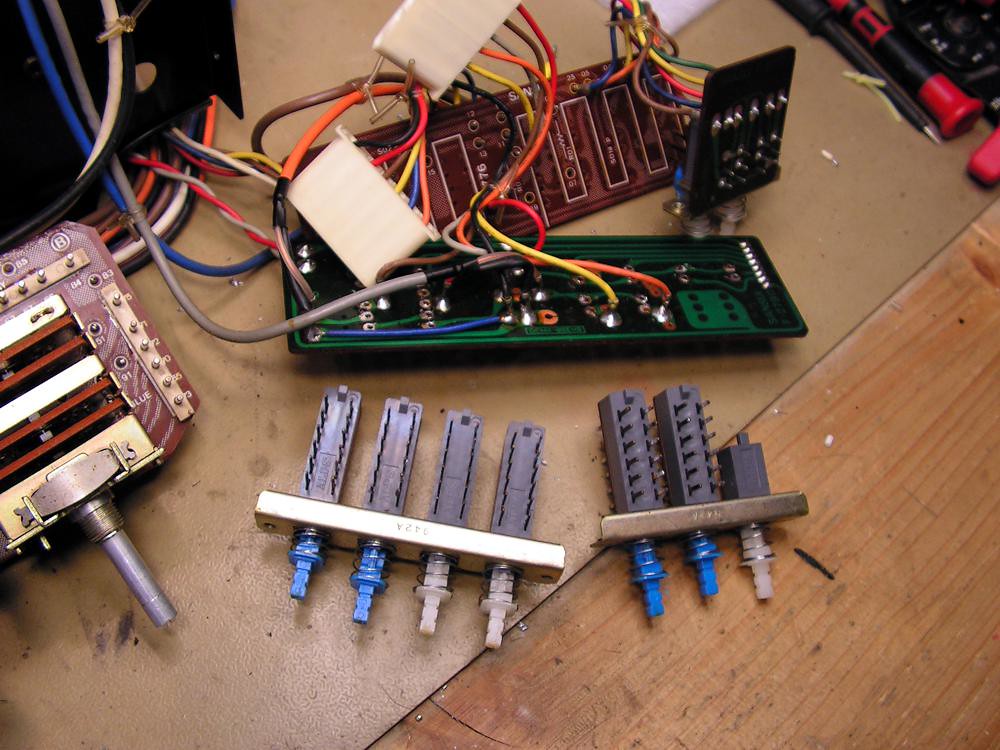
First of all, Flat Amp Board
Subsonic and Jump filter switch
… speakers selector switch…
… cleaned …
…and replaced parts …
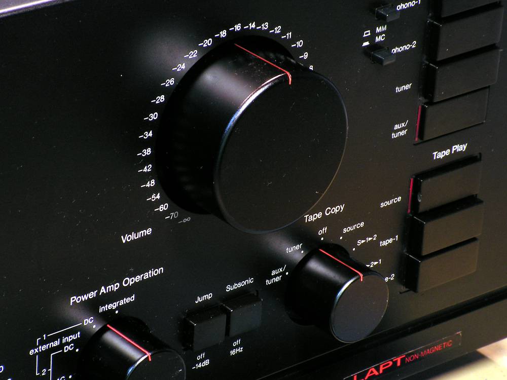
Volume pot
Volume potentiometer is made by Matsushita, and for export AUX1 volume pot is made by ALPS, but the both types are high quality pots.

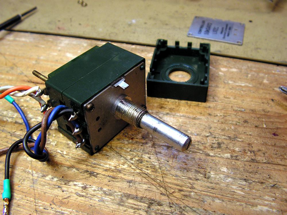
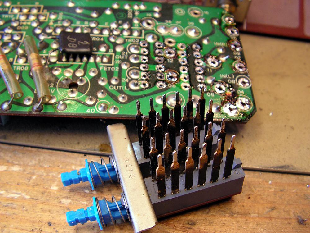
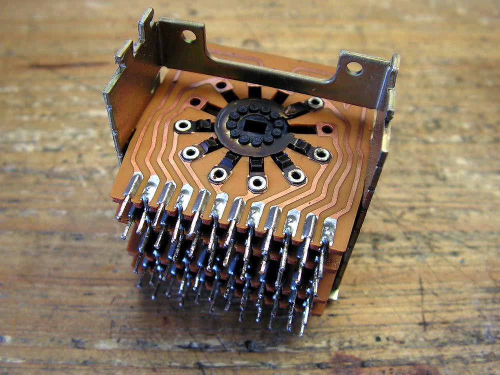
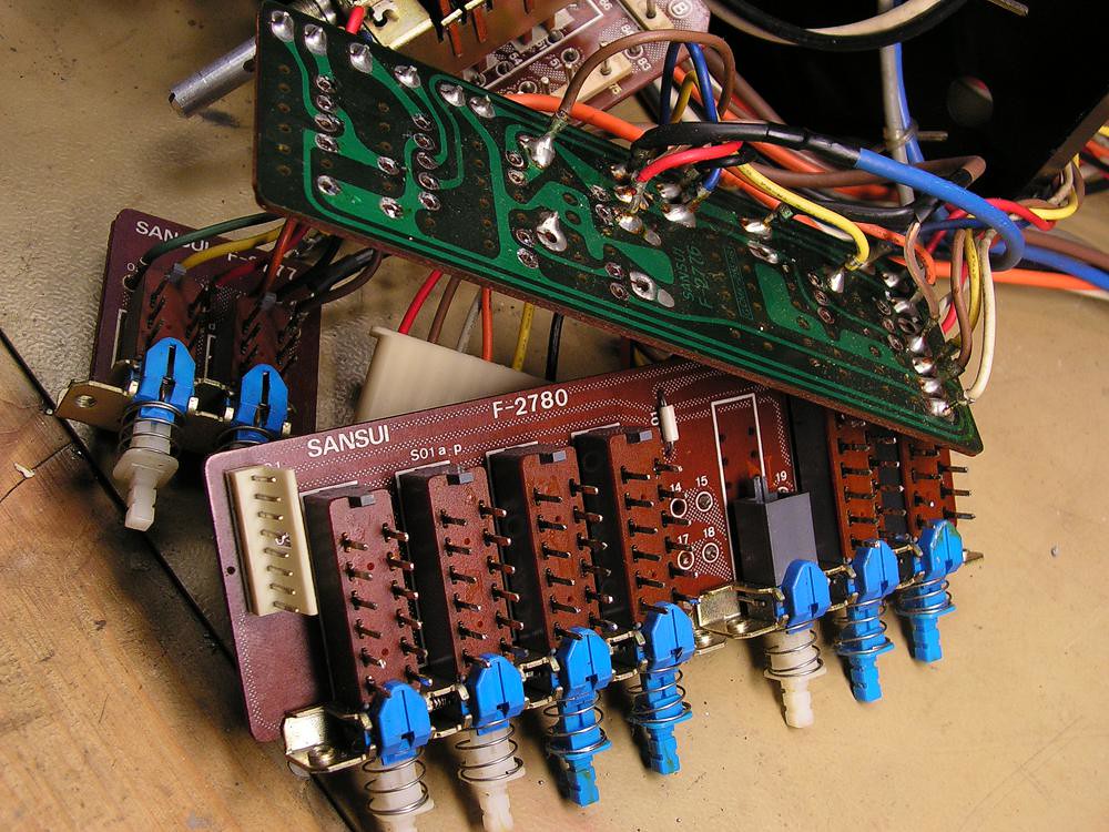
Tape selector
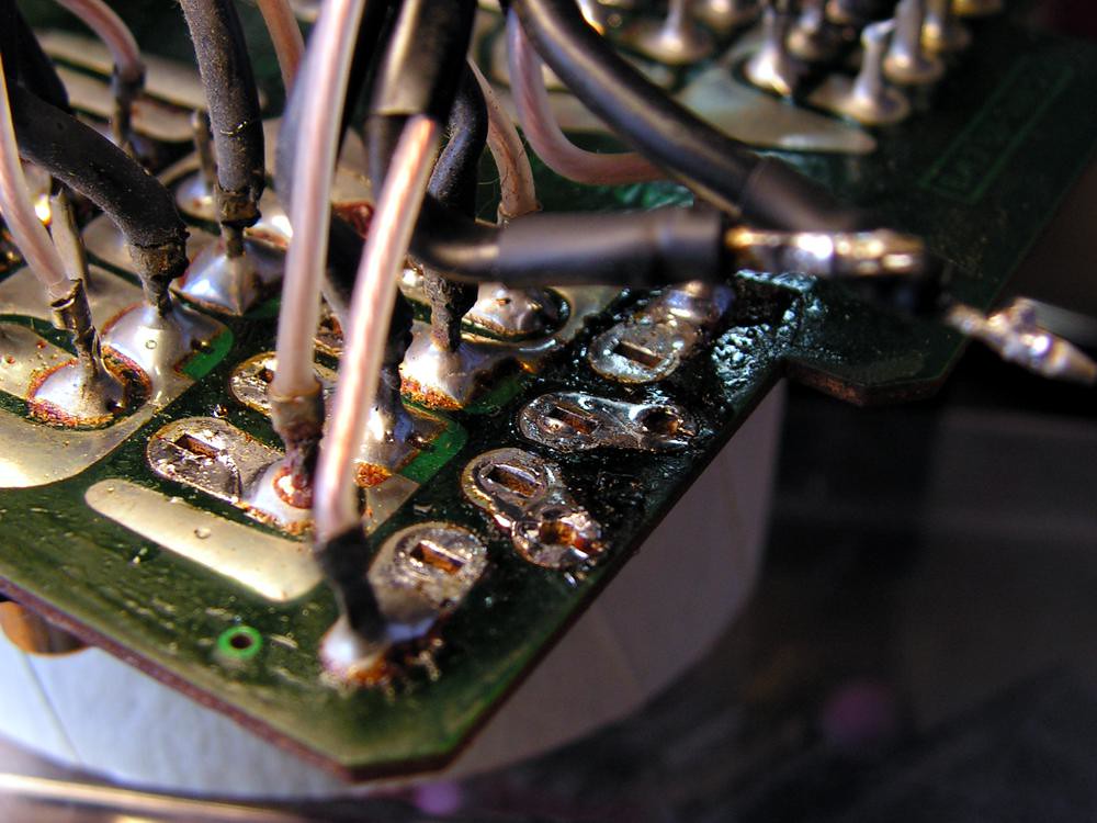
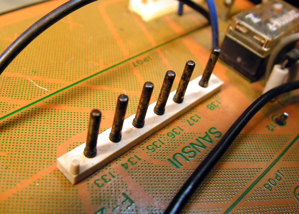
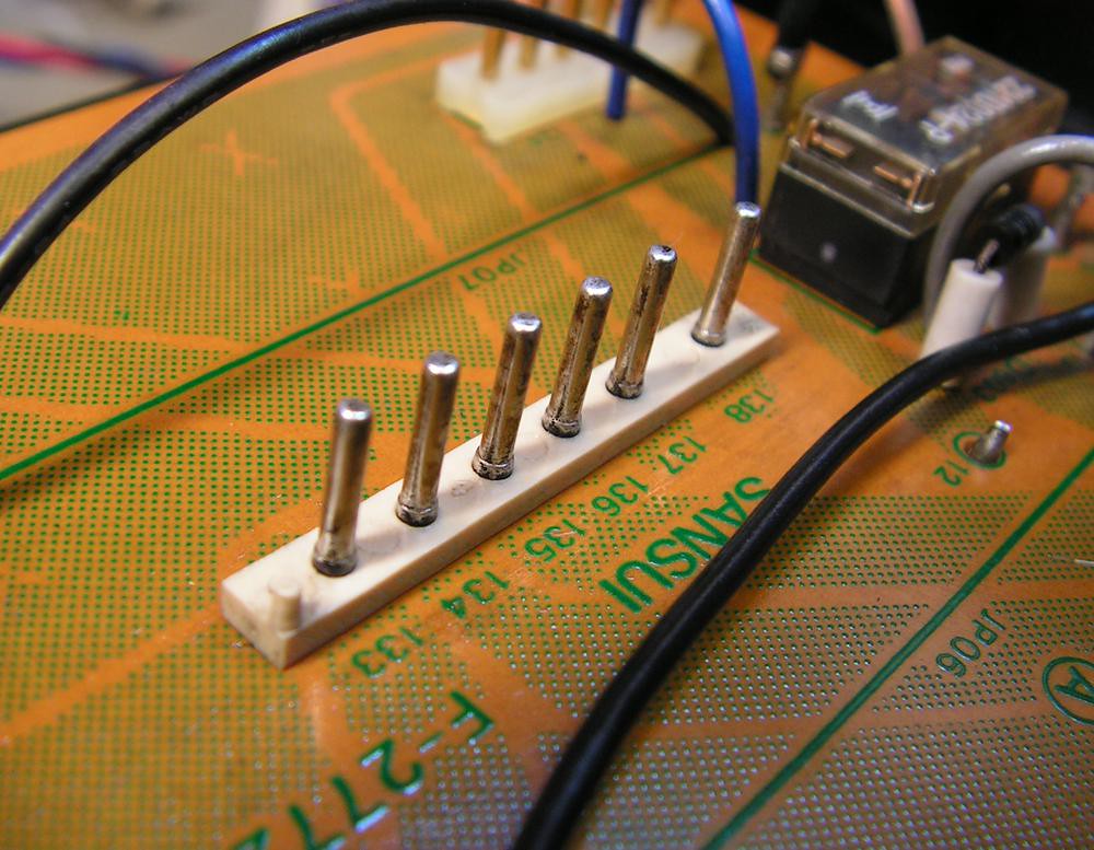
To dismount Tape Selector, first you must desolder all audio cables to get access to pins of selector.
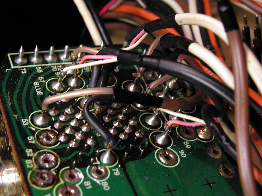
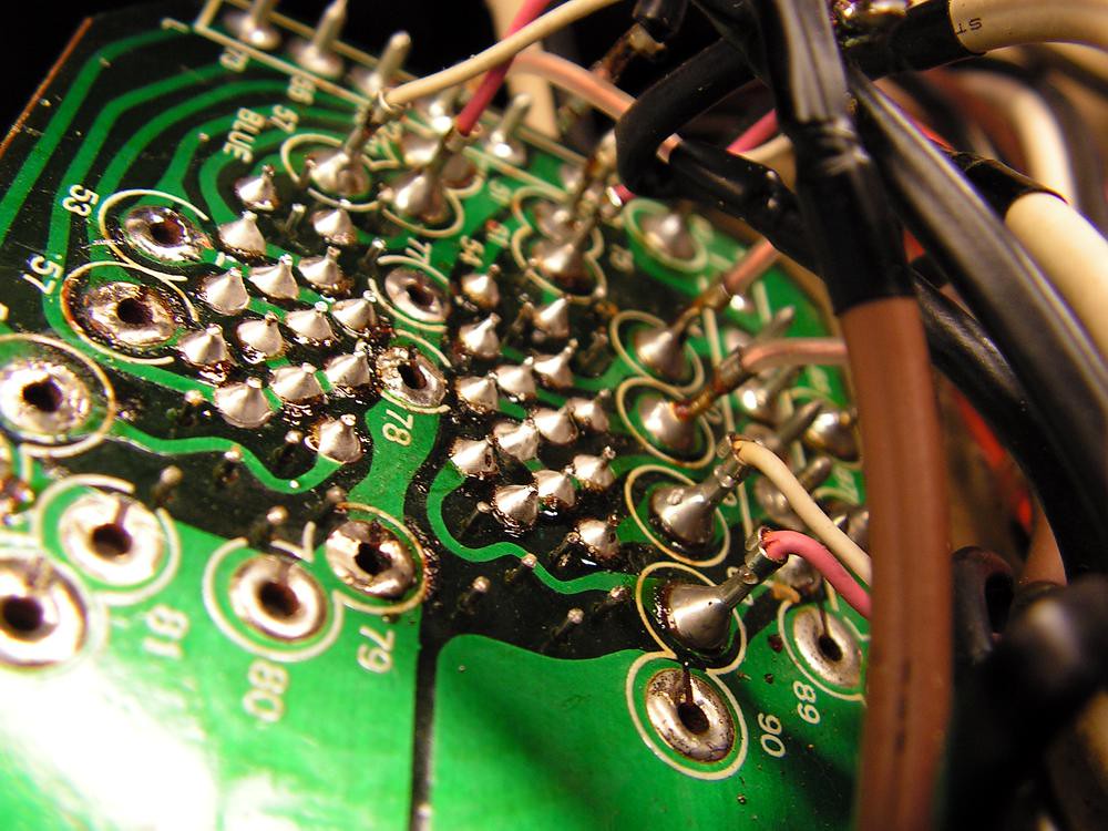
look how at factory soldered those audio wires to the boards
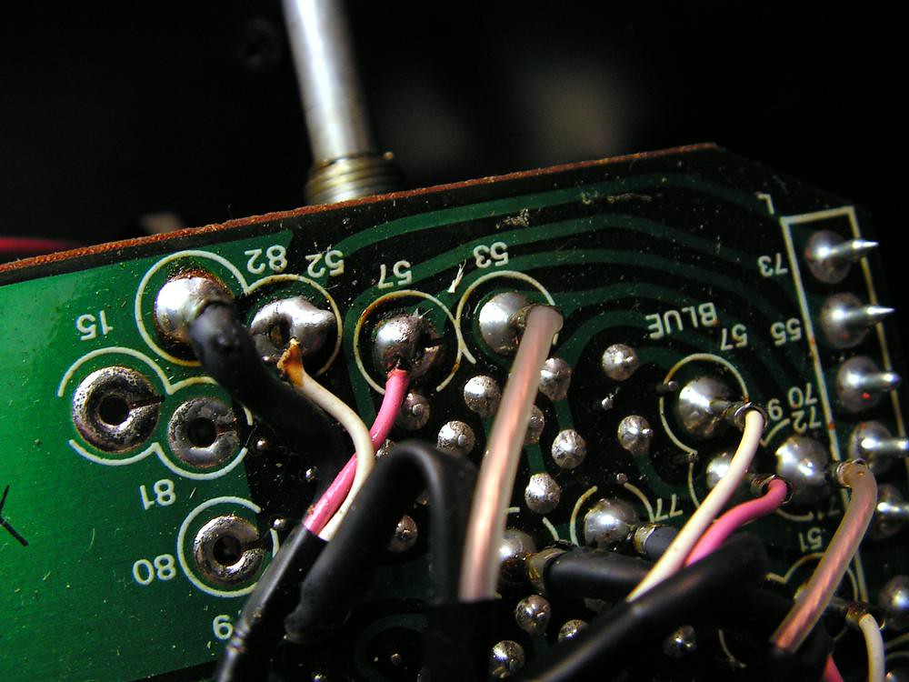
really Sansui sometimes can make things on a bad way …
OK… selector is out…
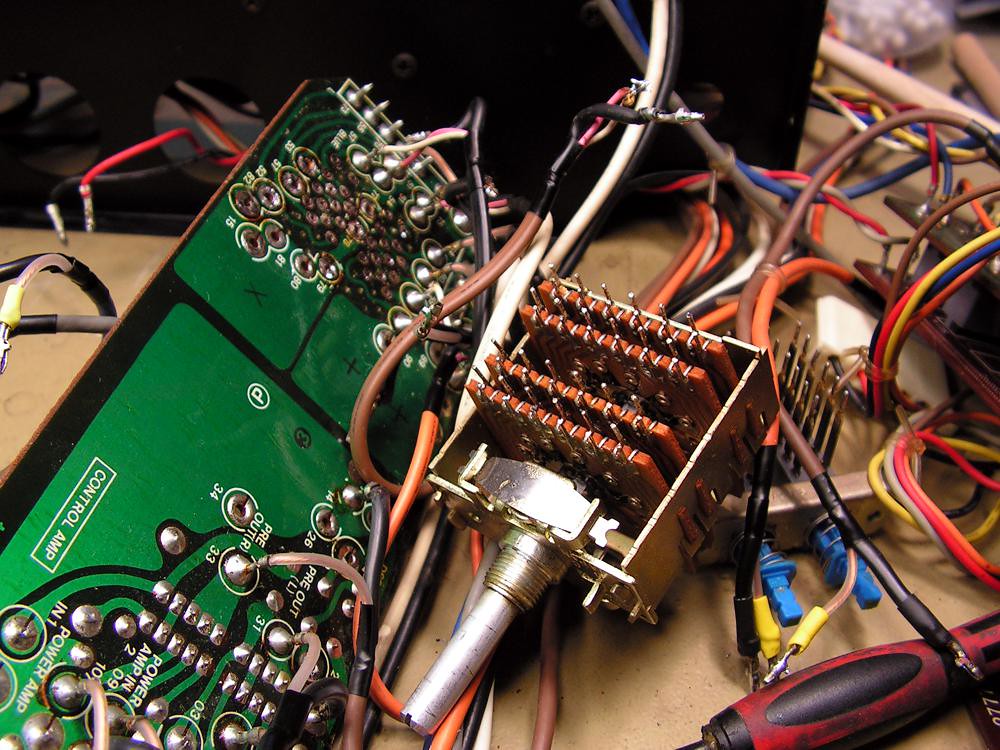
… cleaned…
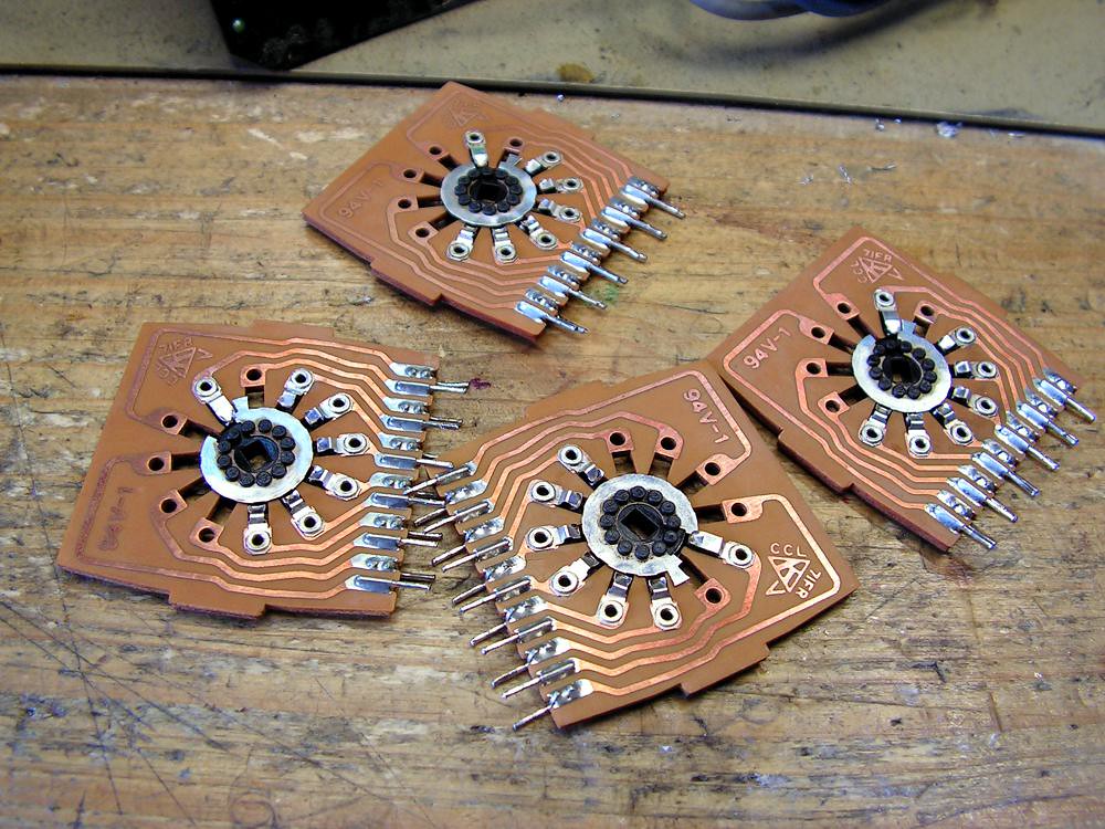
… again soldered on its position …
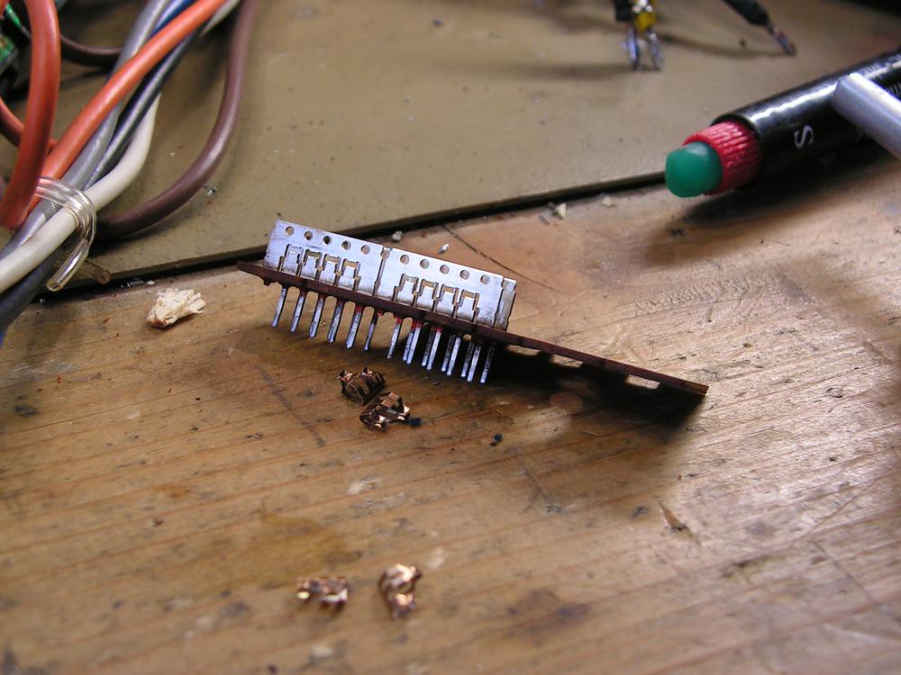
Power Amp Operation Switch
Cleaning Power Amp Operation Switch…
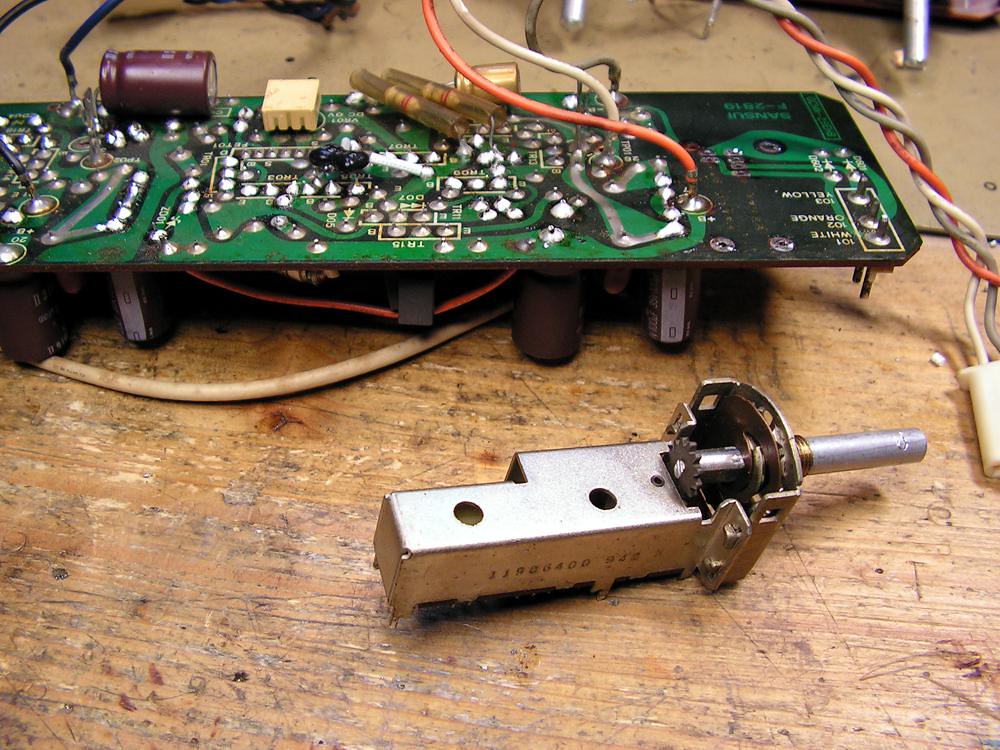
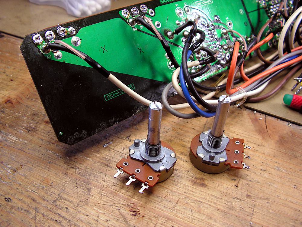
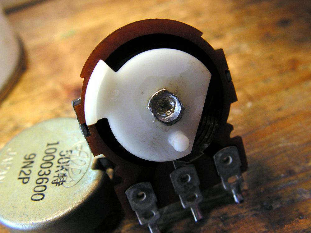
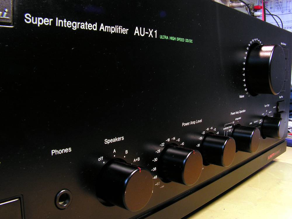
Power Amp Level Potentiometer
Cleaning Power Amp Level Potentiometers
Input Selector and Tape Selector switches
Regulated Power Supply Board
… and again … again… glue…
New capacitors, trimmers…
and what is changed on that board
– 32 electrolytic capacitors
– 4 trimmers
– 24 transistors
– 8 VD1212
– 4 ceramic capacitors
– 2 zener diode
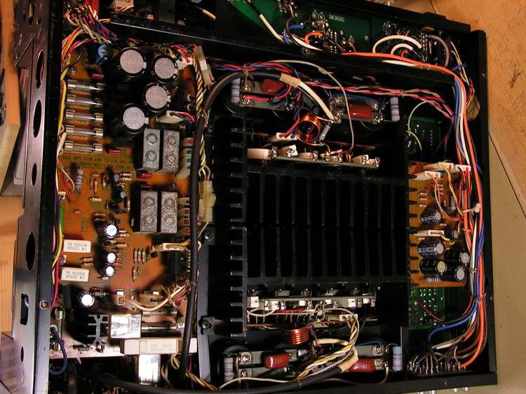
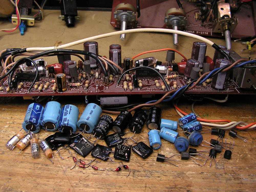
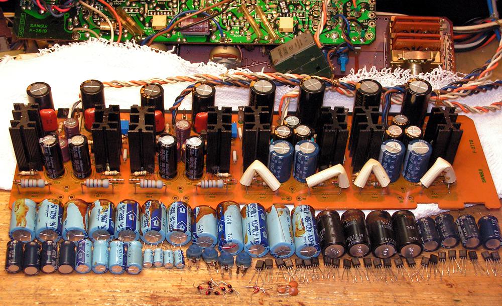
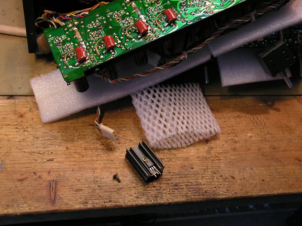
Now, it is time to show you how look like restored the power stage of this amp
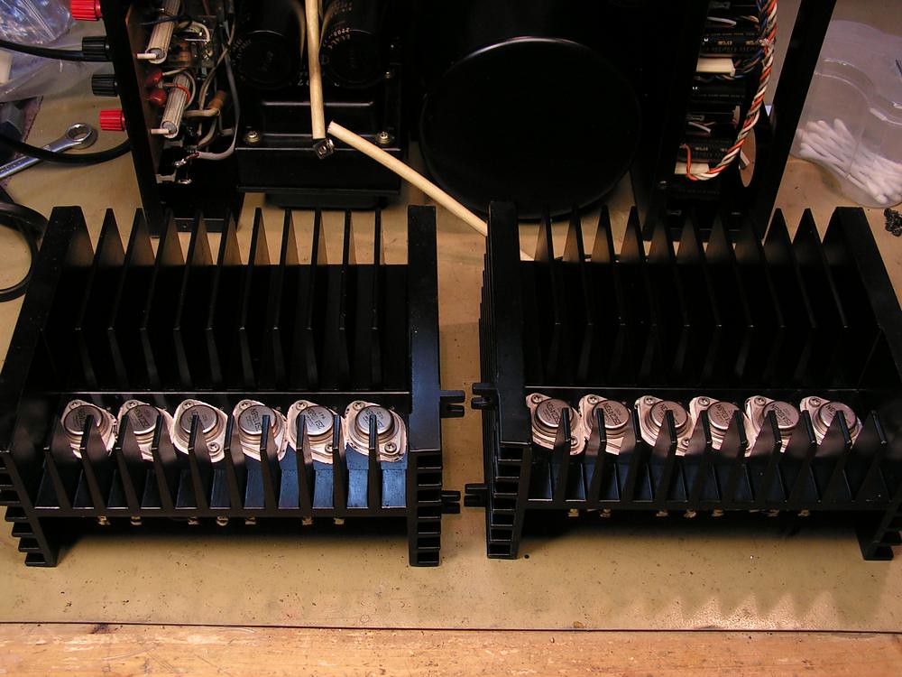
and installed back to the amplifier
Some of bulbs I had to replace…
The new ones are physicaly bigger than old ones, but electrically they are the same.
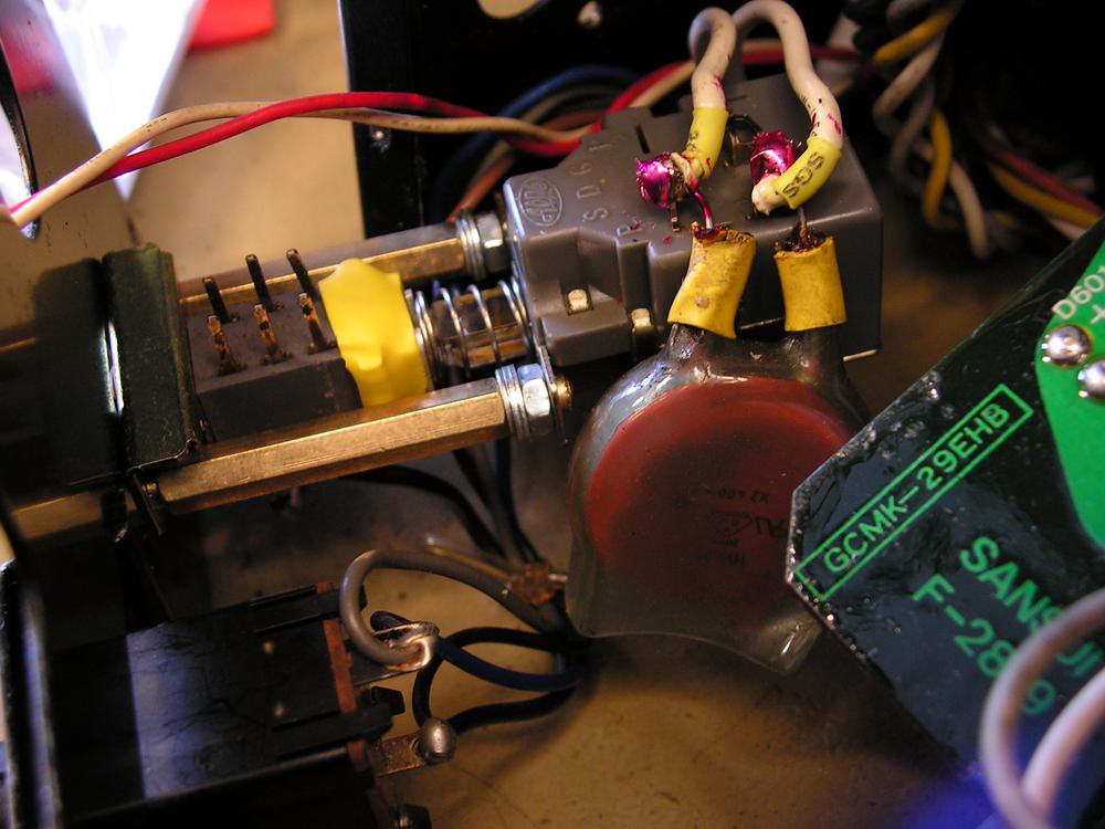
When I tried to adjust Power Supply for MC Phono preamp, I could not adjust one of two 10.50V test points, just because of this transistor, although I have checked all transistors by diode test
But that was not only one problem
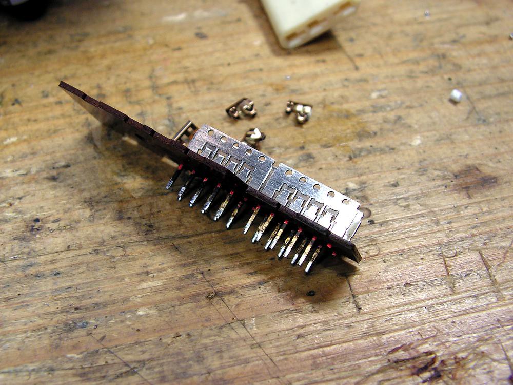
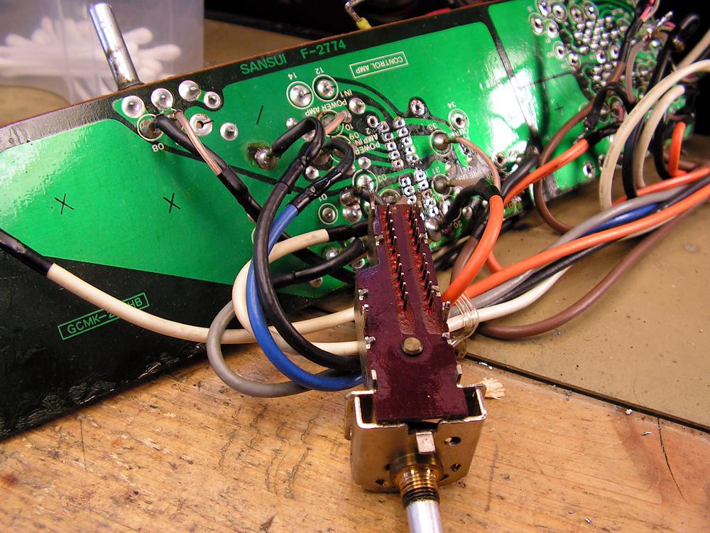
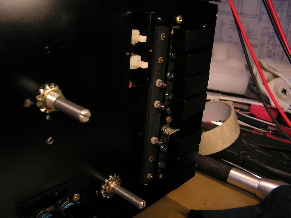
That is power switch, you see it is made of two parts, first low level switch, second high voltage switch. That second high voltage part of this switch had a big problem… take a look at contacts
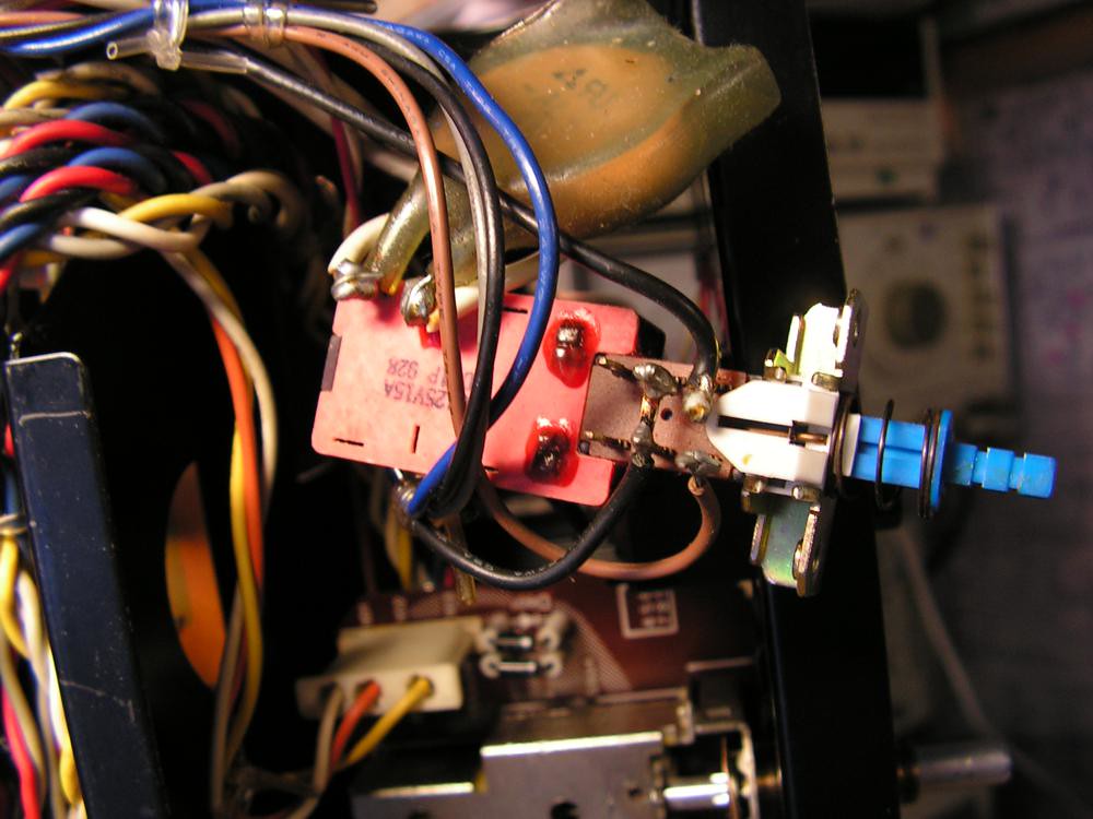
take a look at contacts
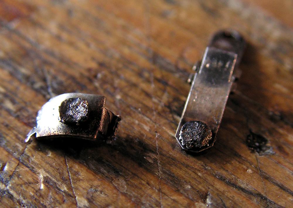
That can’t be fixed, so I must replace that switch… because in that time it was hard to find that type switch (today I have it NOS!), I fixed it on this way:
you see, first part is the same low level switch, and second part is new genuine ALPS switch.
And finally…
Ladies and Gentlemen…. Sansui AUX1 !!!!
And please look at the next picture:
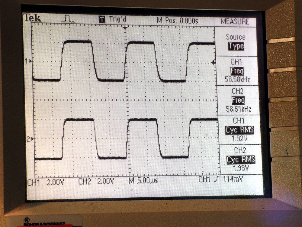
That is square signal frequency of 60kHz taken from speakers output with dummy 8 ohm resistor. You see, it is stable and very fast.
And at the end, what I have changed during that restoration
plus Dual Cap capacitors….
Oct 27, 2012