Sansui AU20000 – second unit restoration
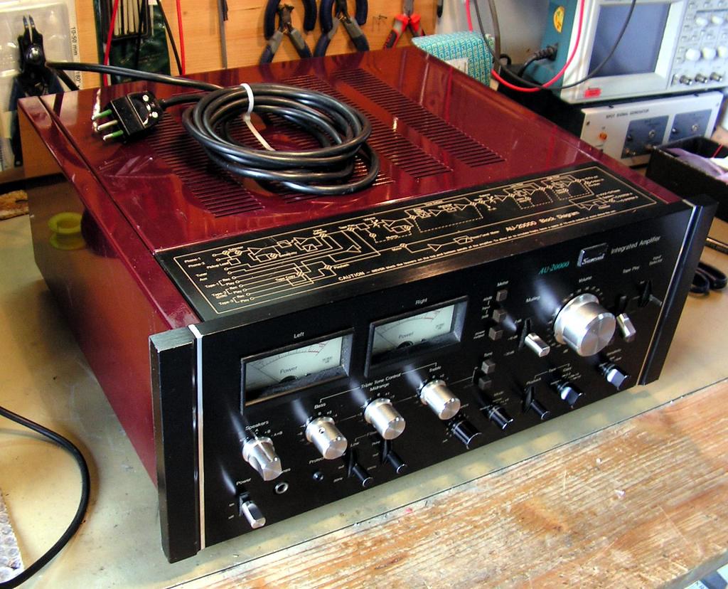
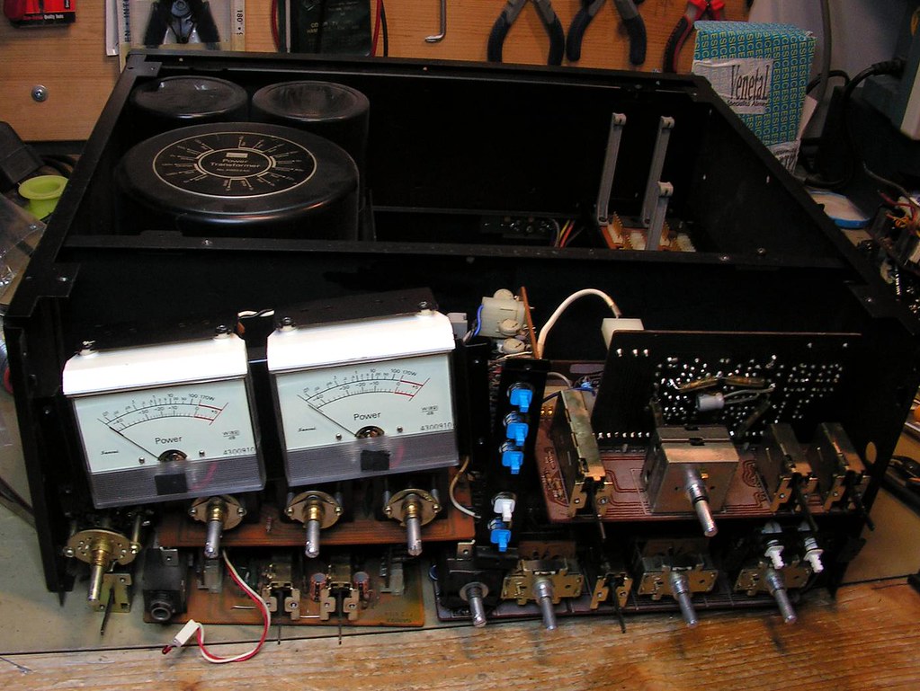
Another big Sansui on my bench… Sansui AU20000!
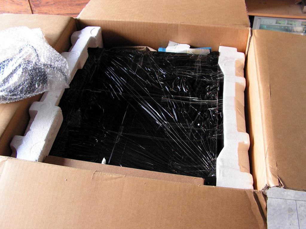
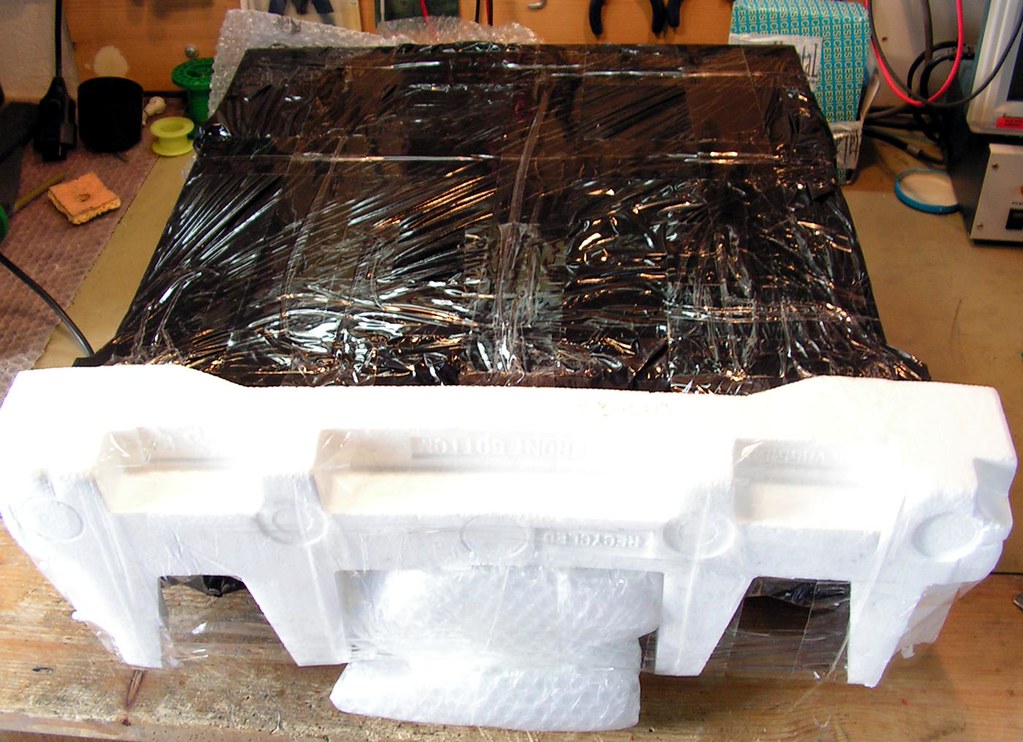
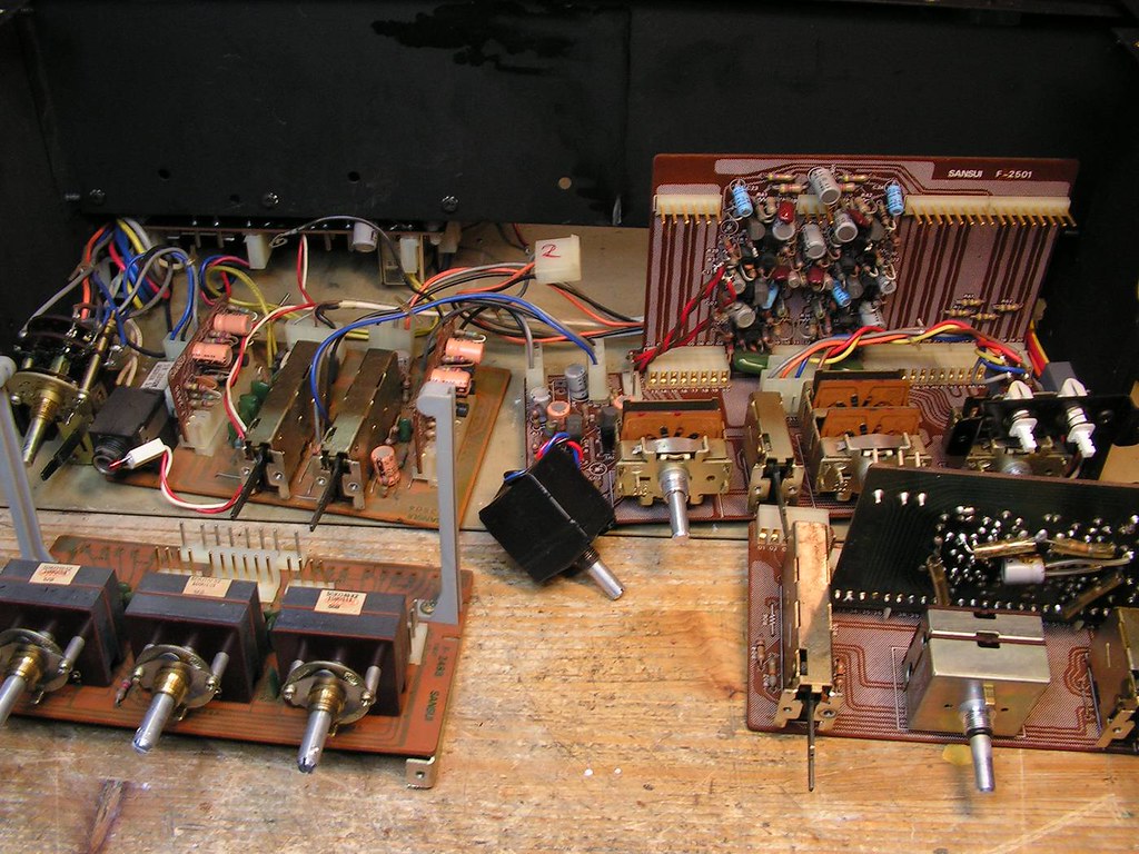
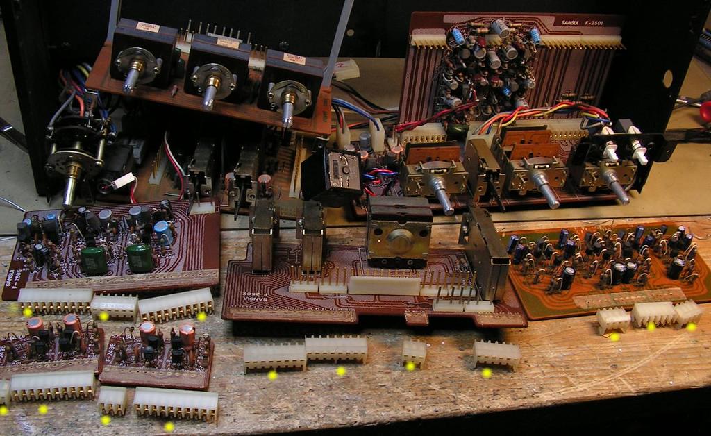
Amplifier has some issues, and someone tried to fix it in the past… but first some pictures how I got it…
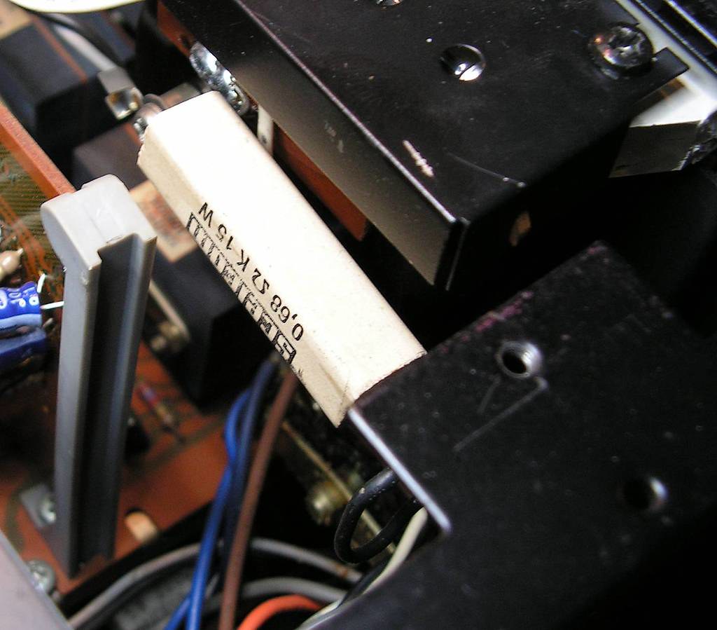
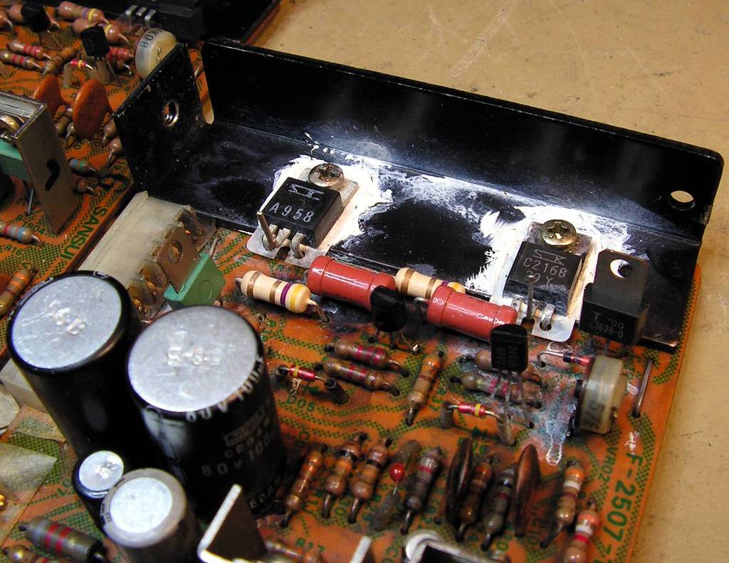
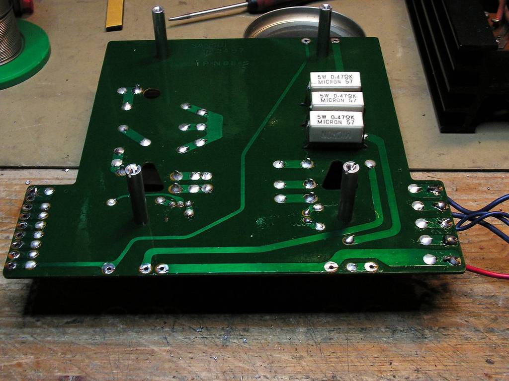
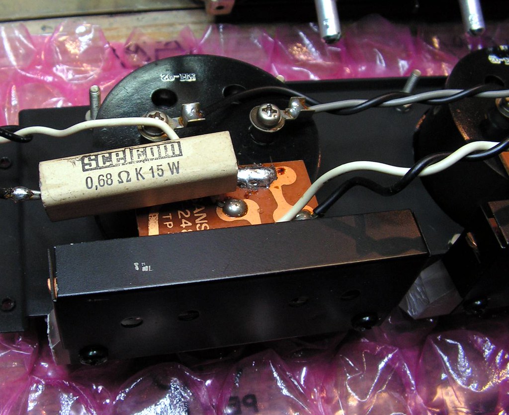
First what I noticed is this ceramic power resistor connected to the power meters (?!)… I will see about that later….
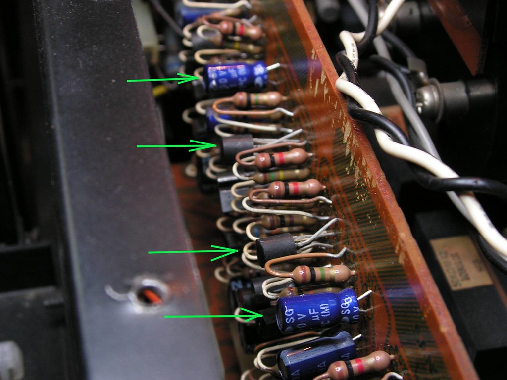
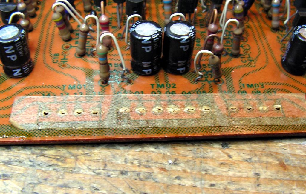
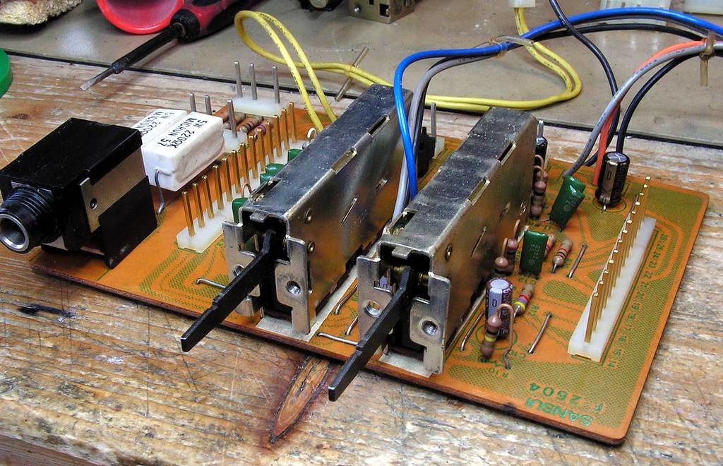
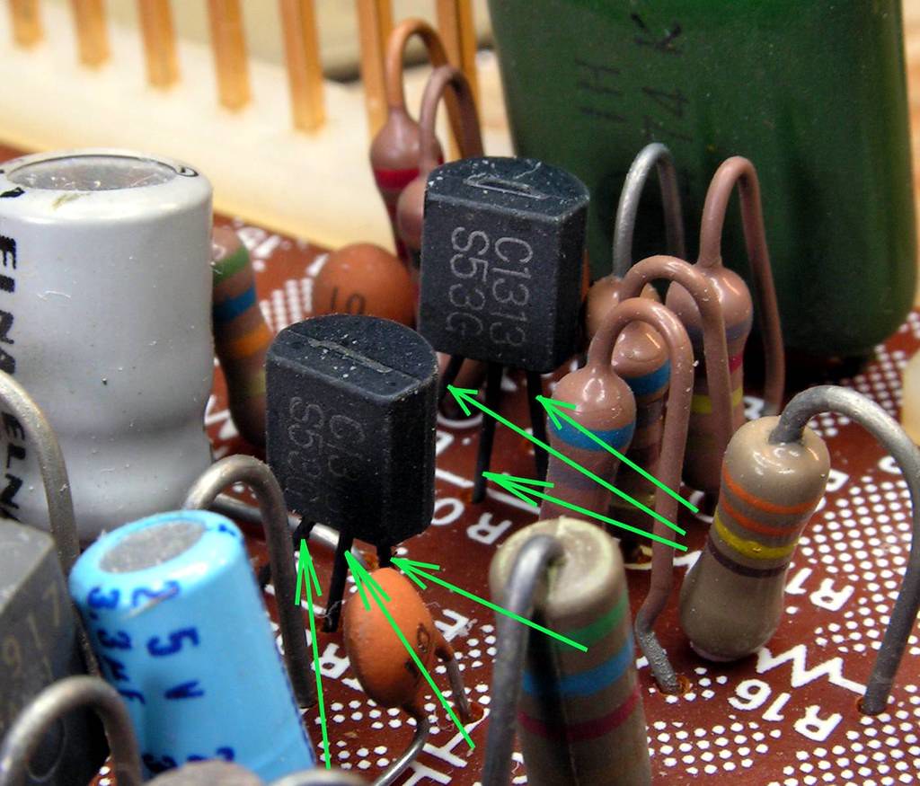
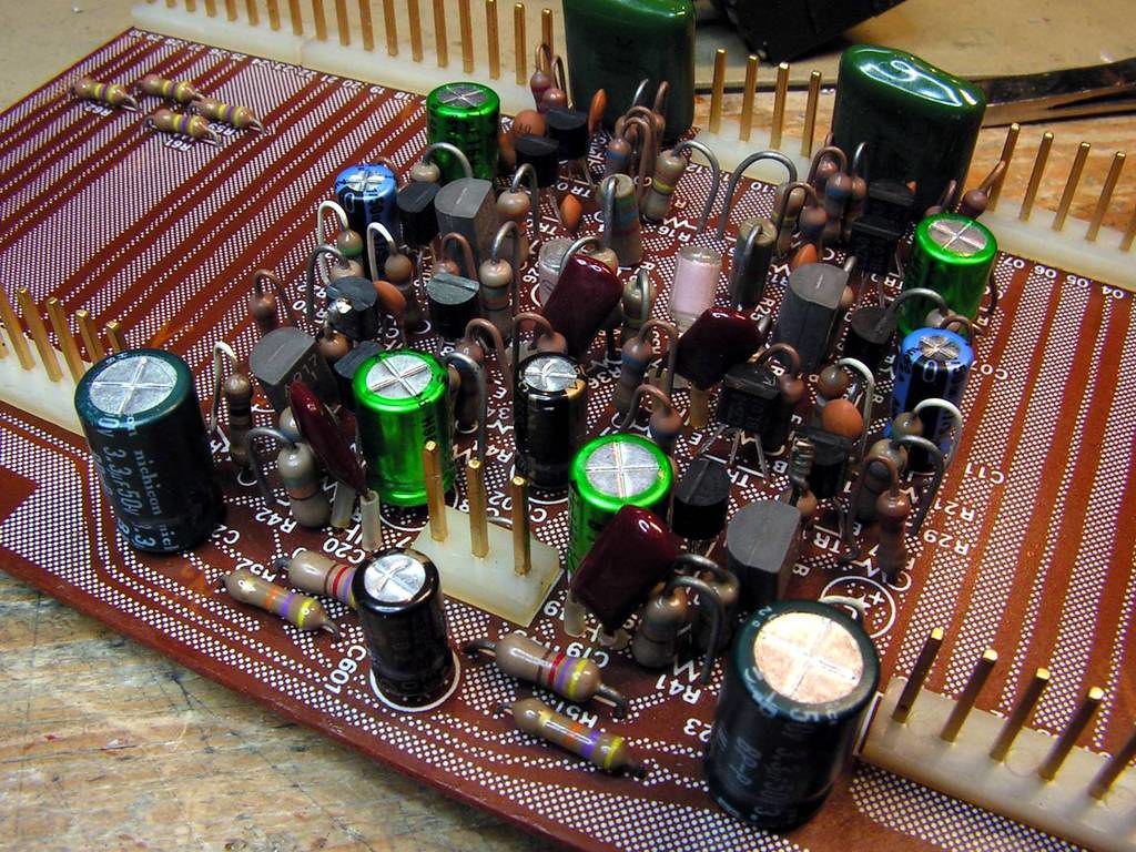
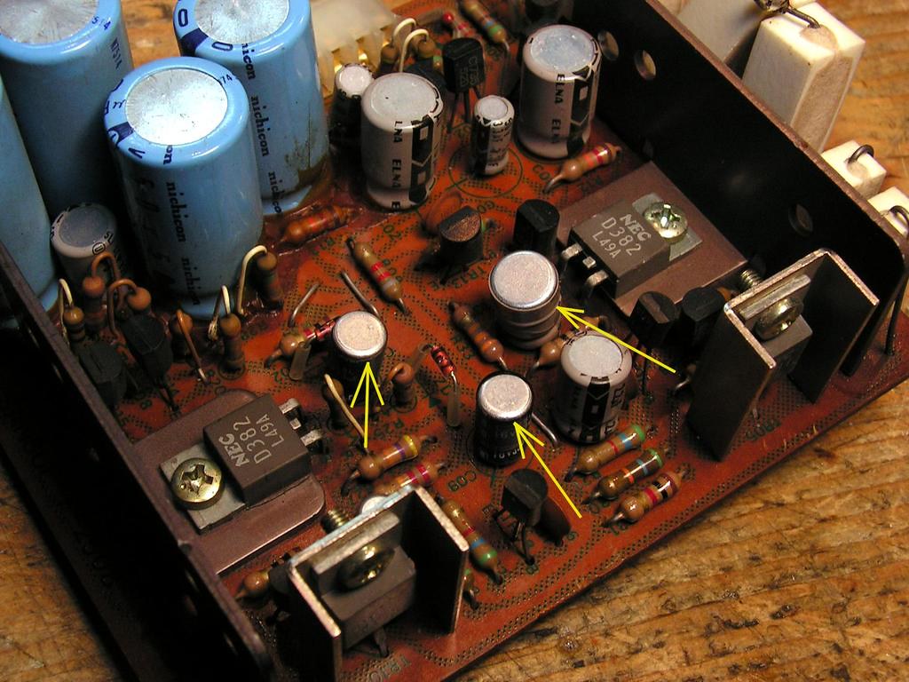
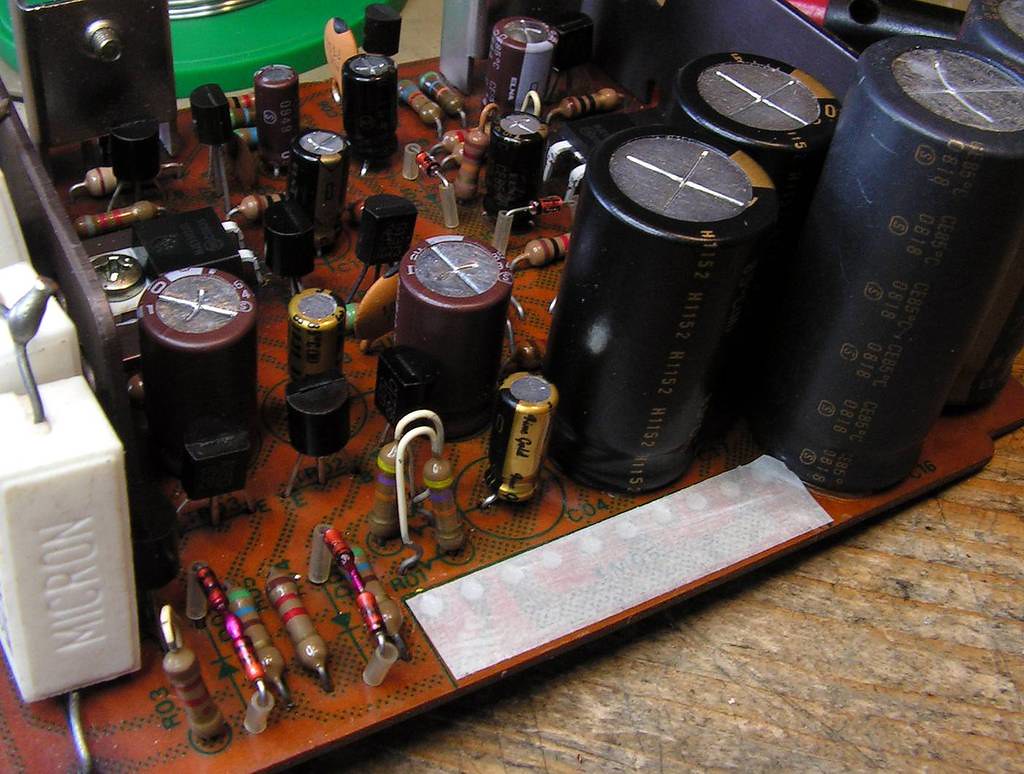
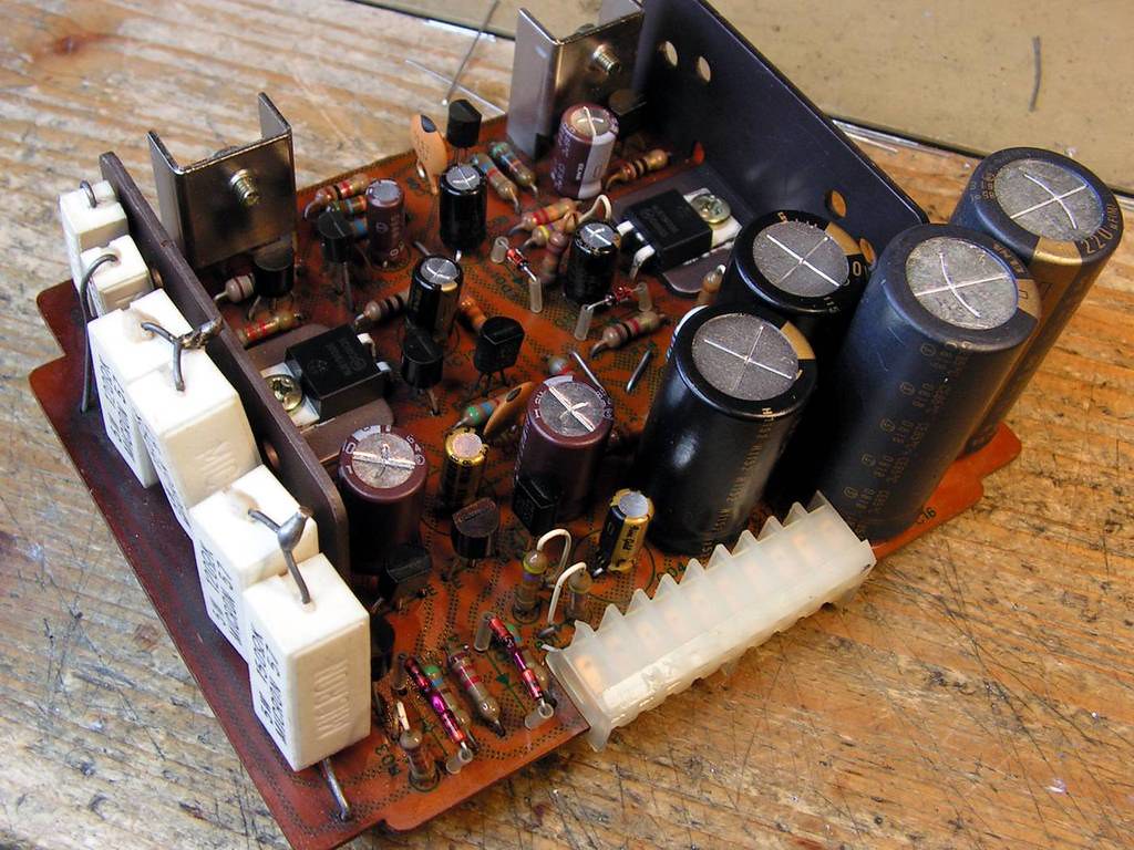
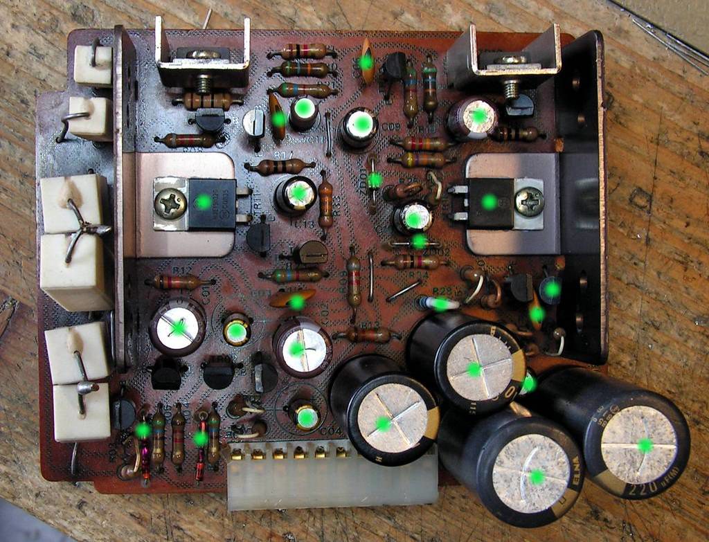
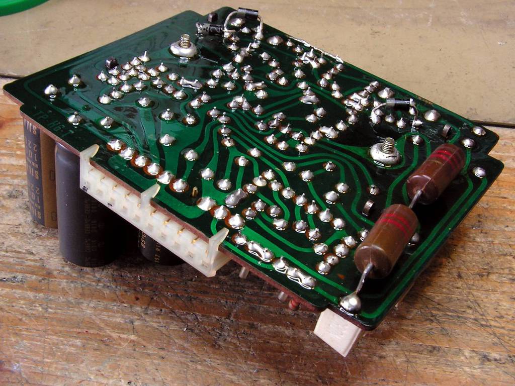
Second, that Tone amplifier board has some new electrolytic capacitors and some new small signal transistors… that will be checked later too…
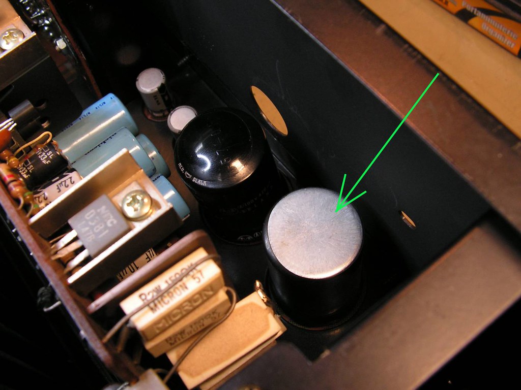
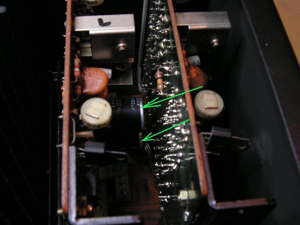
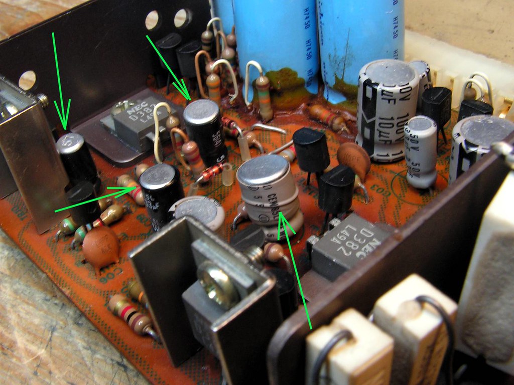
Amplifier has some overheating problems, look how looks like some electrolytic capacitors ….
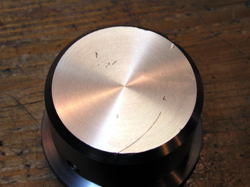
Volume knob has some scratches…
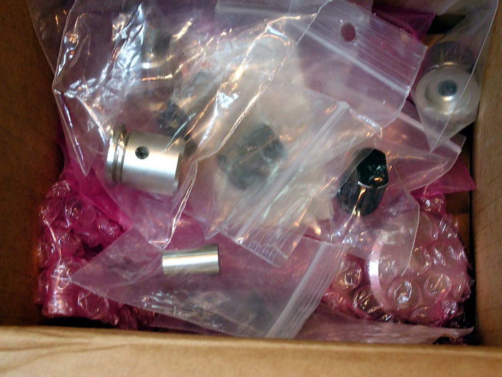
So, to prevent more damages on aluminum knobs of amplifier, I am always keeping them at nylon bags after I removed them from amplifier…
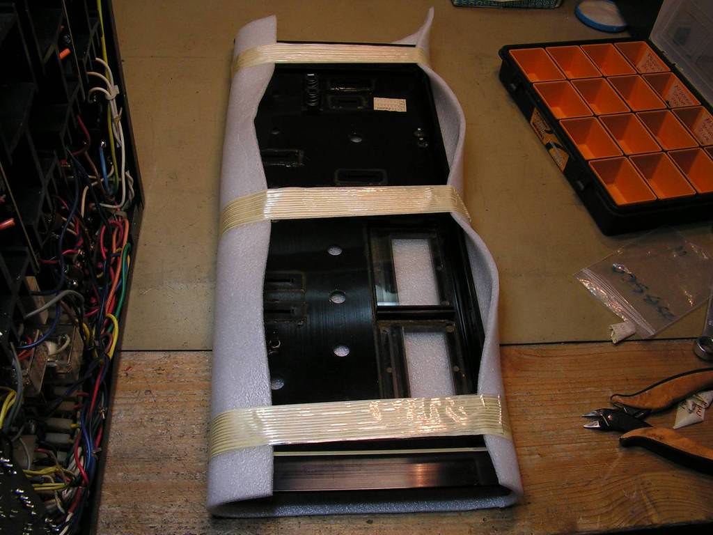
The same thing with front plate… it is protected from damage…
Driver boards… one fixed on not so nice way
Really not so nice….
even the legs of the exchanged electronic elements are so long (technician forgot to cut them)…
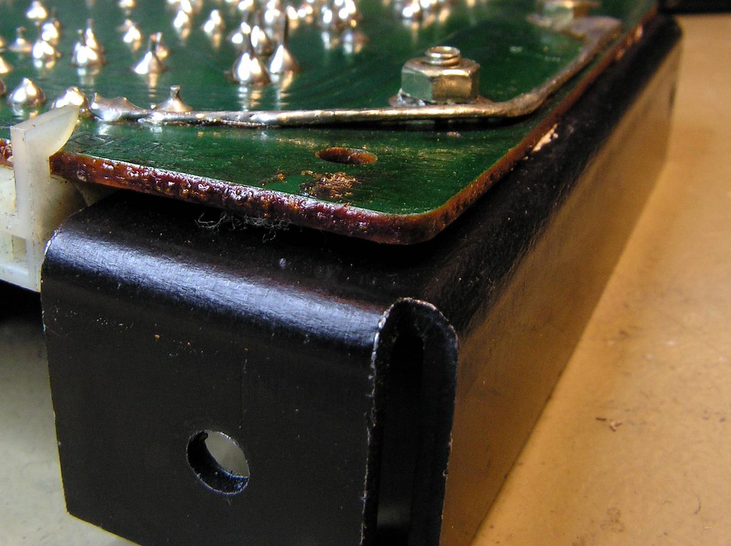
The corner one of driver board…
because the technician was not so careful…
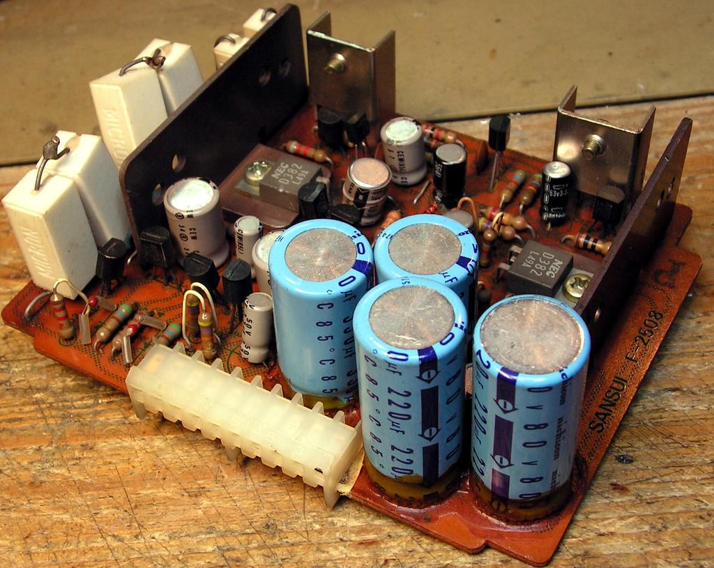
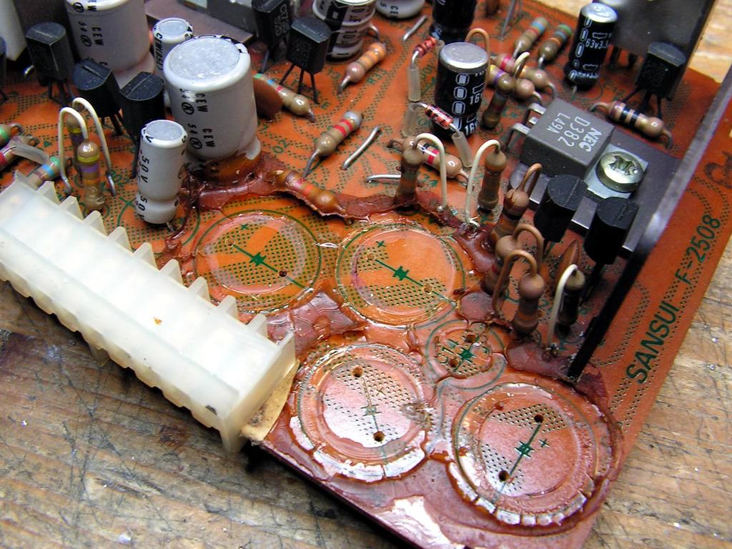
Again overheating problem… this time on Regulated Power Supply board
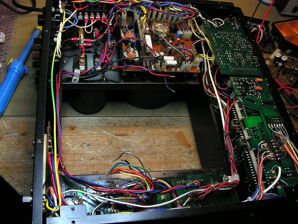
… and current state of amplifier…
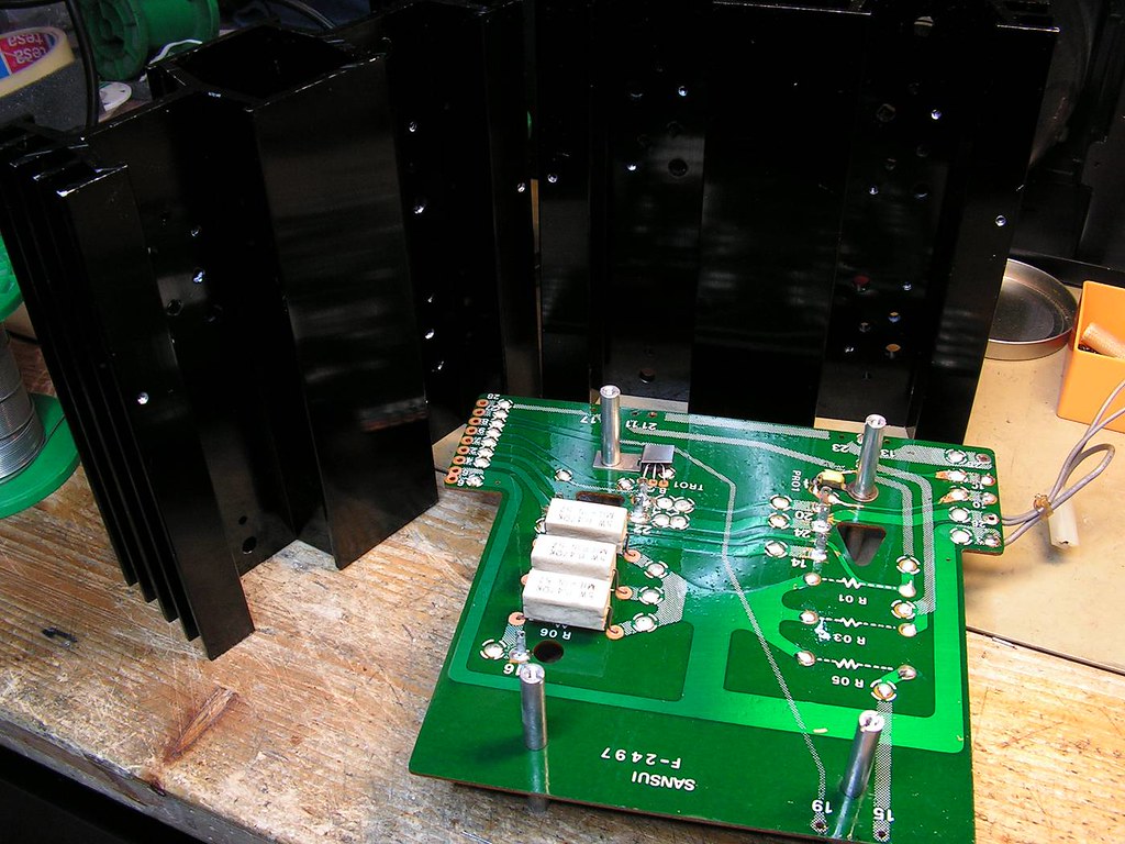
One of two power stage module
Again… what to say….
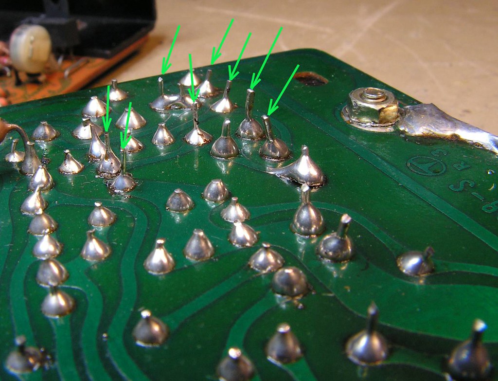
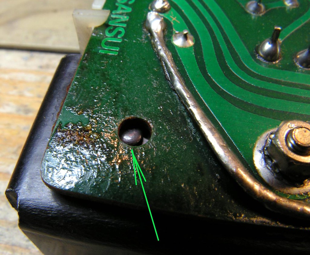
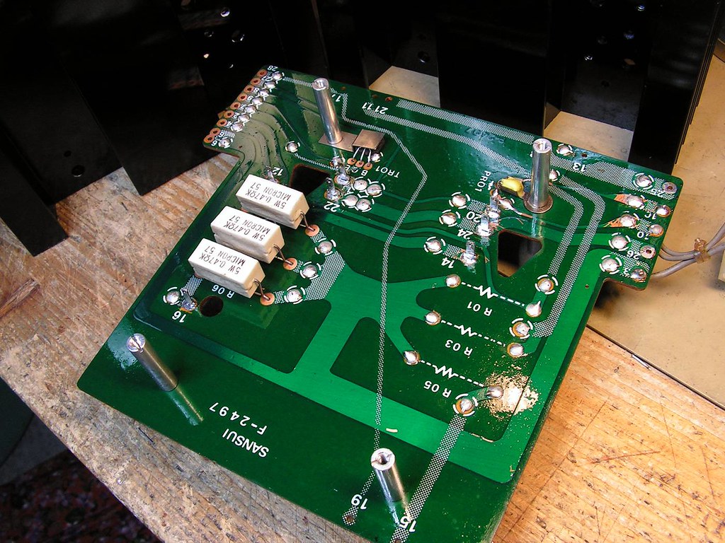
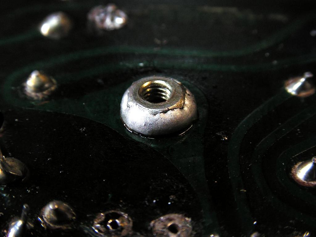
This detail is very important at those kind of boards…
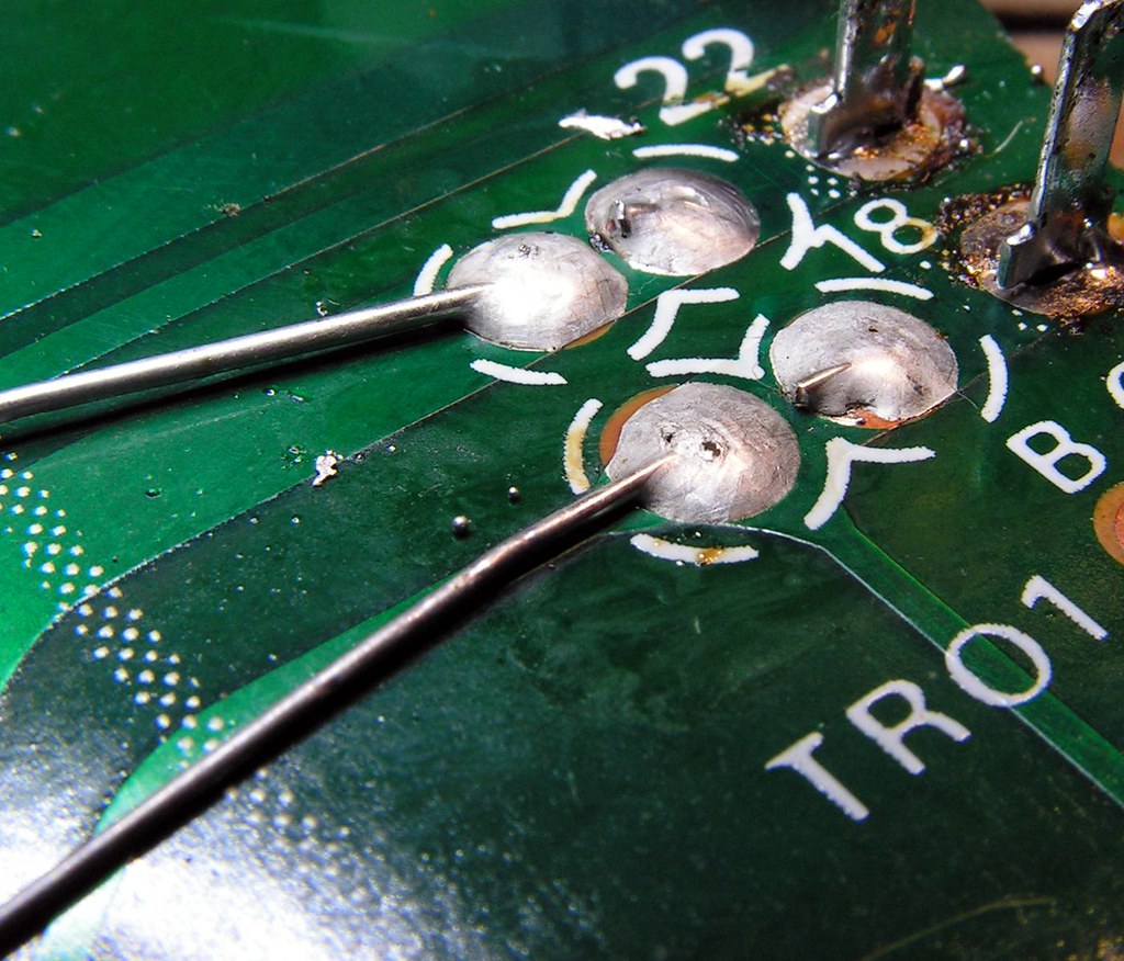
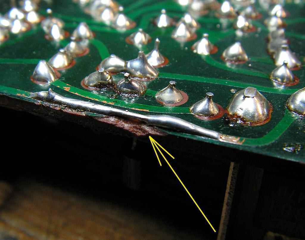
That is pass through electrical connection between two side of board. As you see, that board has two side printed circuits, and electrical connection was made by that rivet. Sometime that way of connection can make connection problem, so I always remove old solder, place through hole a piece of wire, and then resolder all
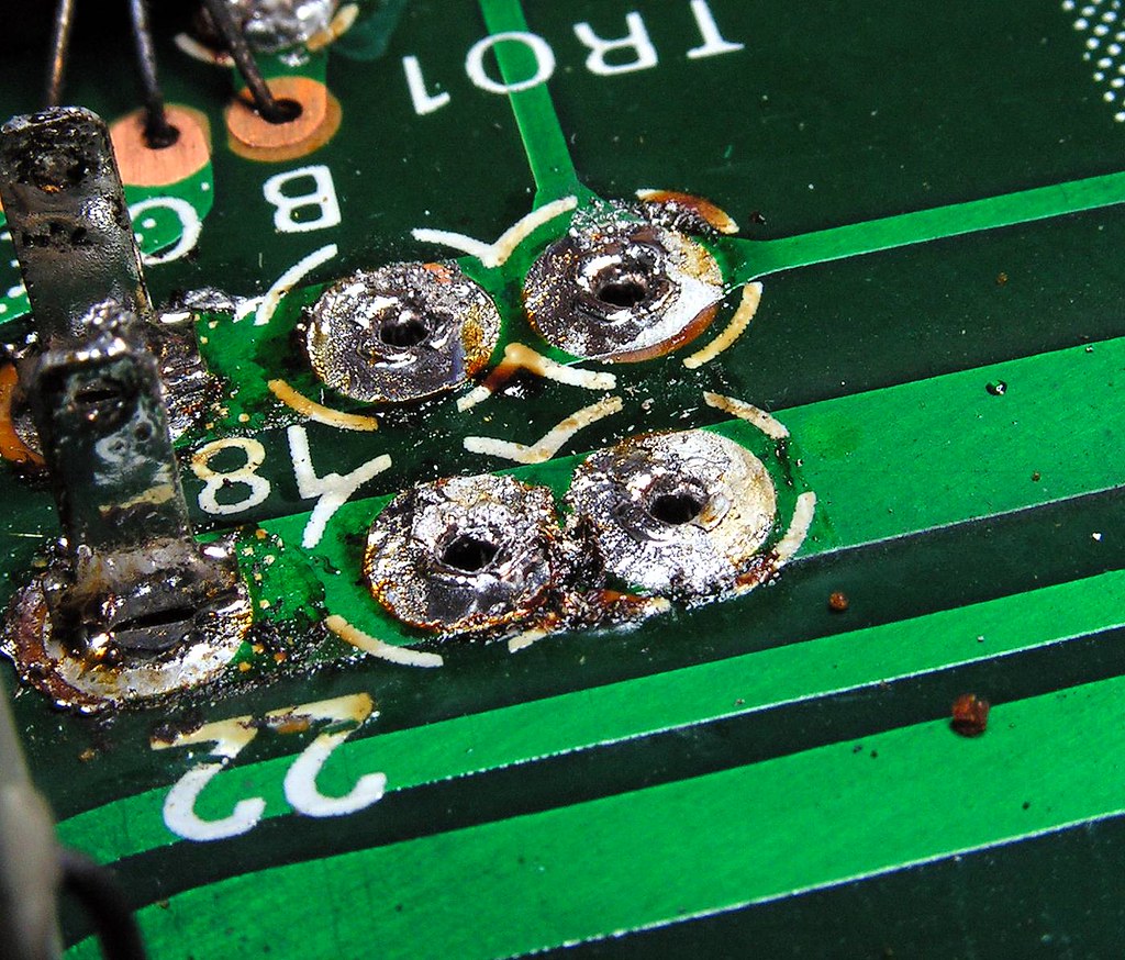
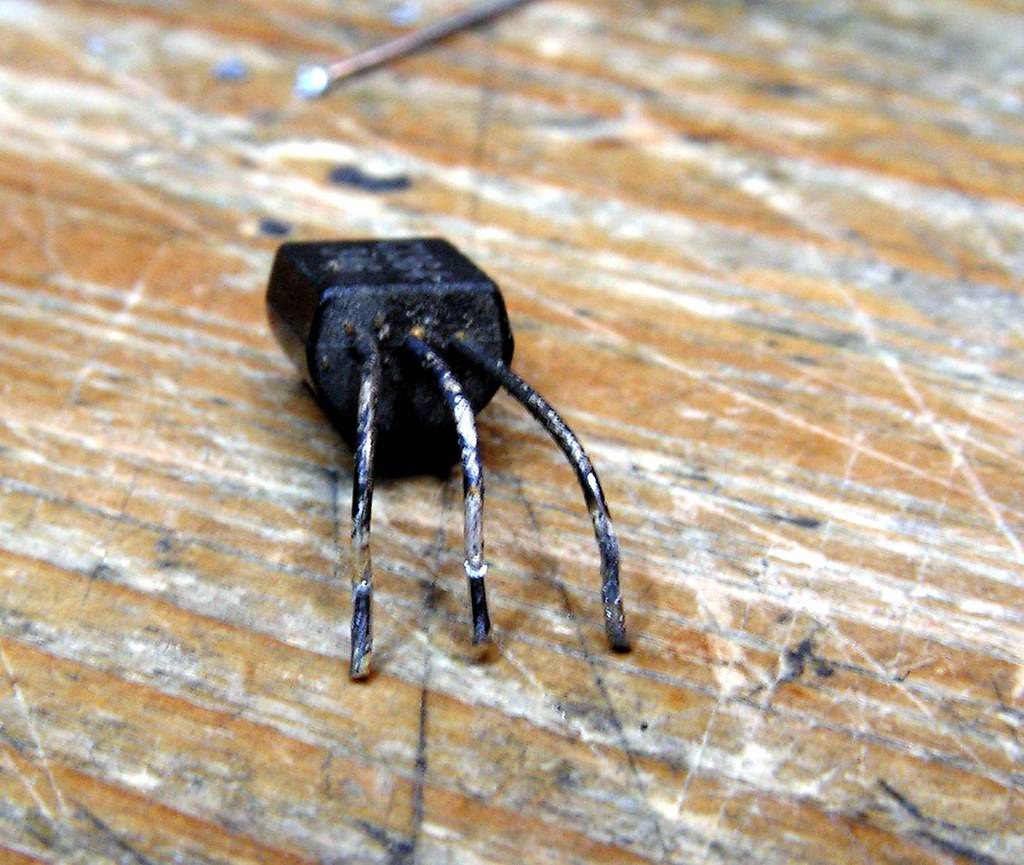
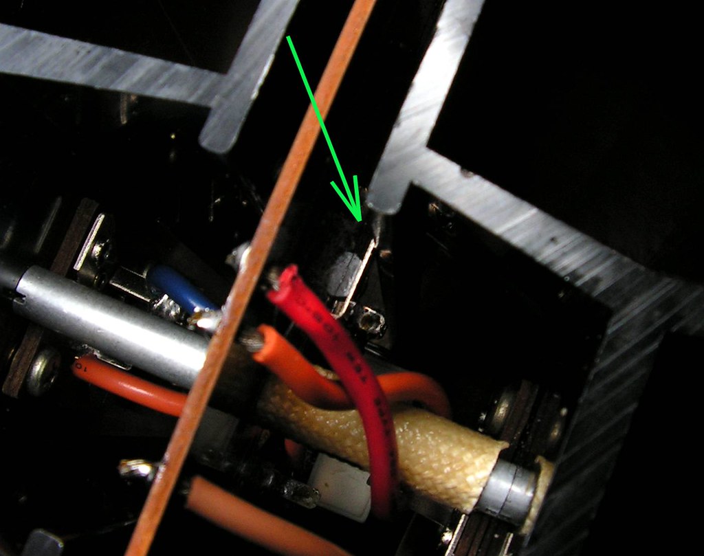
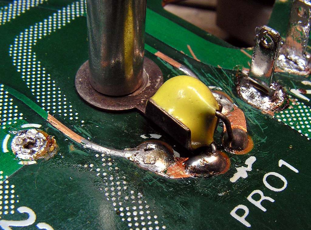
Another problem is this 2SC1364 BIAS transistor. Please look the next picture how it looks like:
It has a good chance to get that corrosion inside of plastic body, and then every kind of issues are possible!
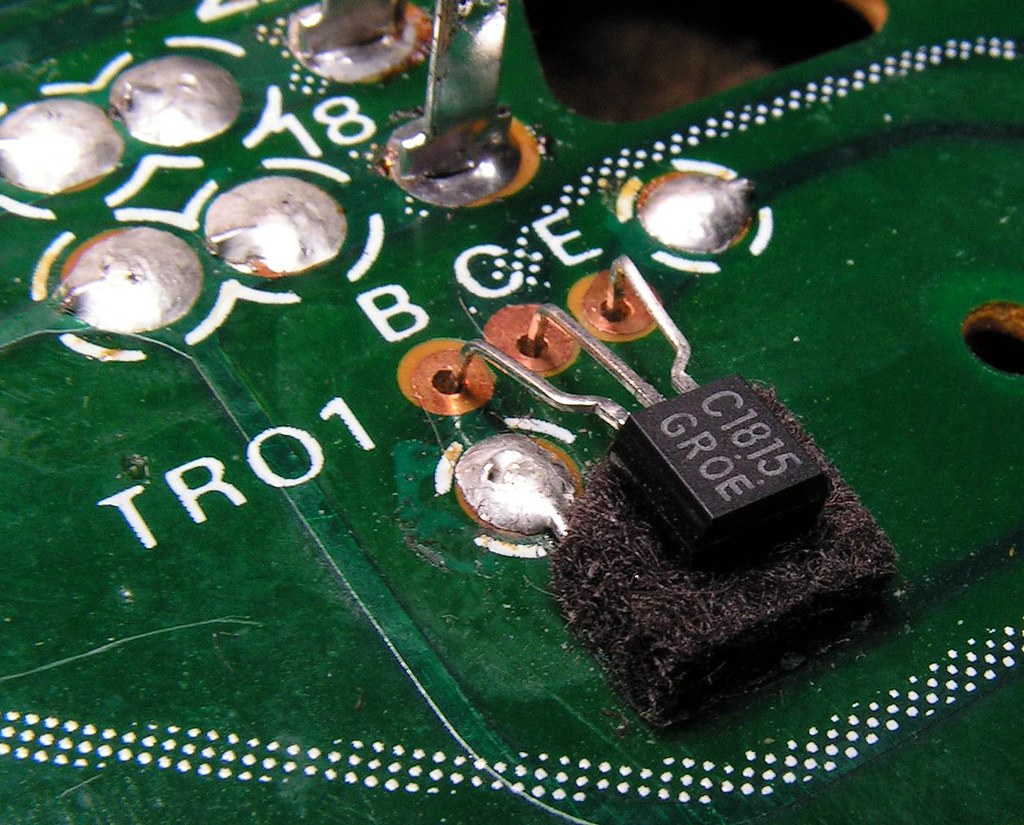
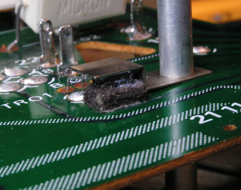
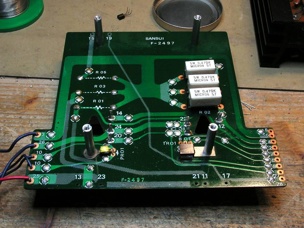
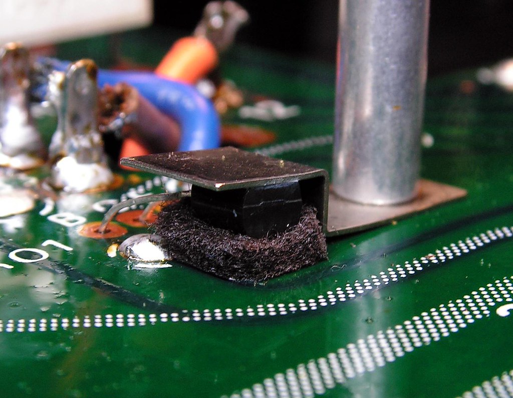
So I decided to change it by Toshiba 2SC1815, but… it would be not interesting that here I have one another problem… today production of small signal transistors has plastic body smaller than that 2SC136, and that is very important, because BIAS transistor should have a good mechanical contact to that metal piece to get heat transfer from heat sink of power transistors. I solved that problem on this way:
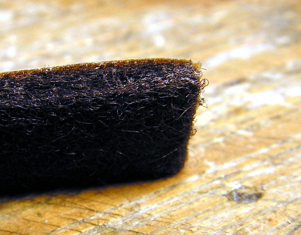
This is not a foam, this is some synthetic self-adhesive material what you can buy for putting to end of the legs for chair or table or some heavy devices. I have that material at legs of my G22000 to prevent damage of my furniture. It is very stable for pressure.
Now you see on which way the BIAS transistor detect a temperature of the heat-sink .
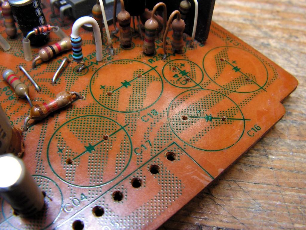
First board of the power stage is finished (the both sides)
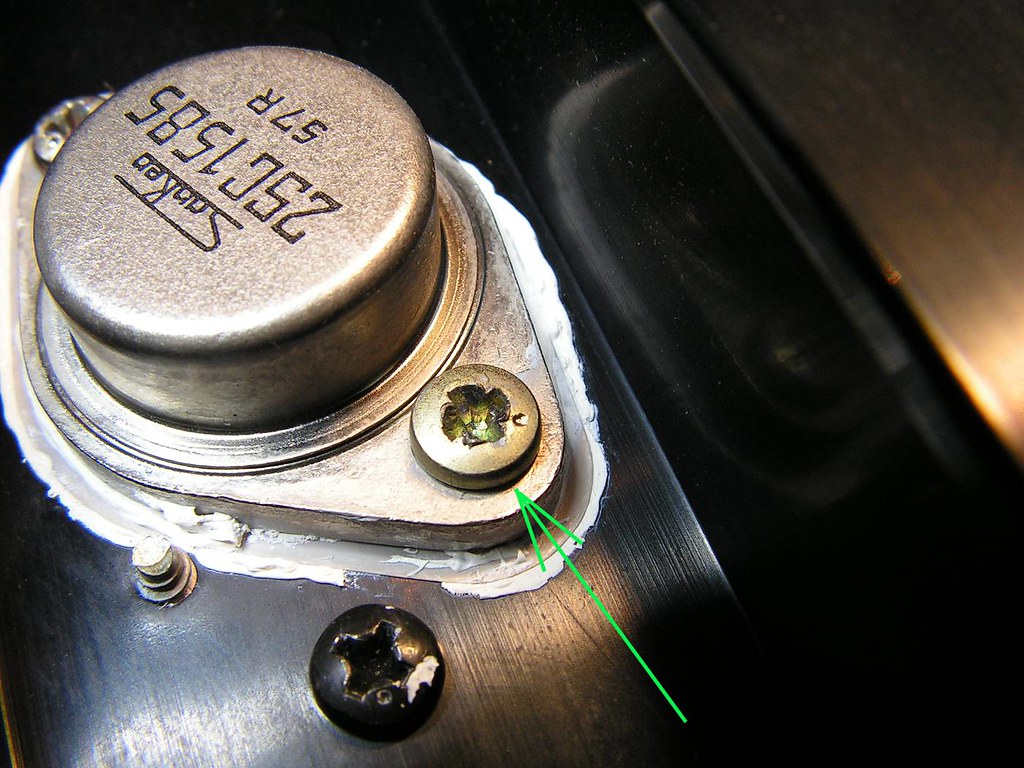
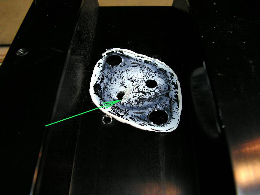
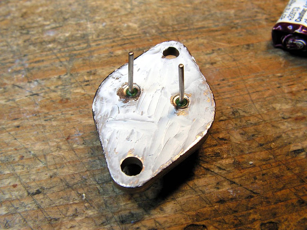
I really can’t understand why some technician putting so much that thermal grease, maybe he thinks that it would be better heat transfer, but not! That is worse, and in other hand, so much thermal grease could make an electrical contact problems between transistor and socket.
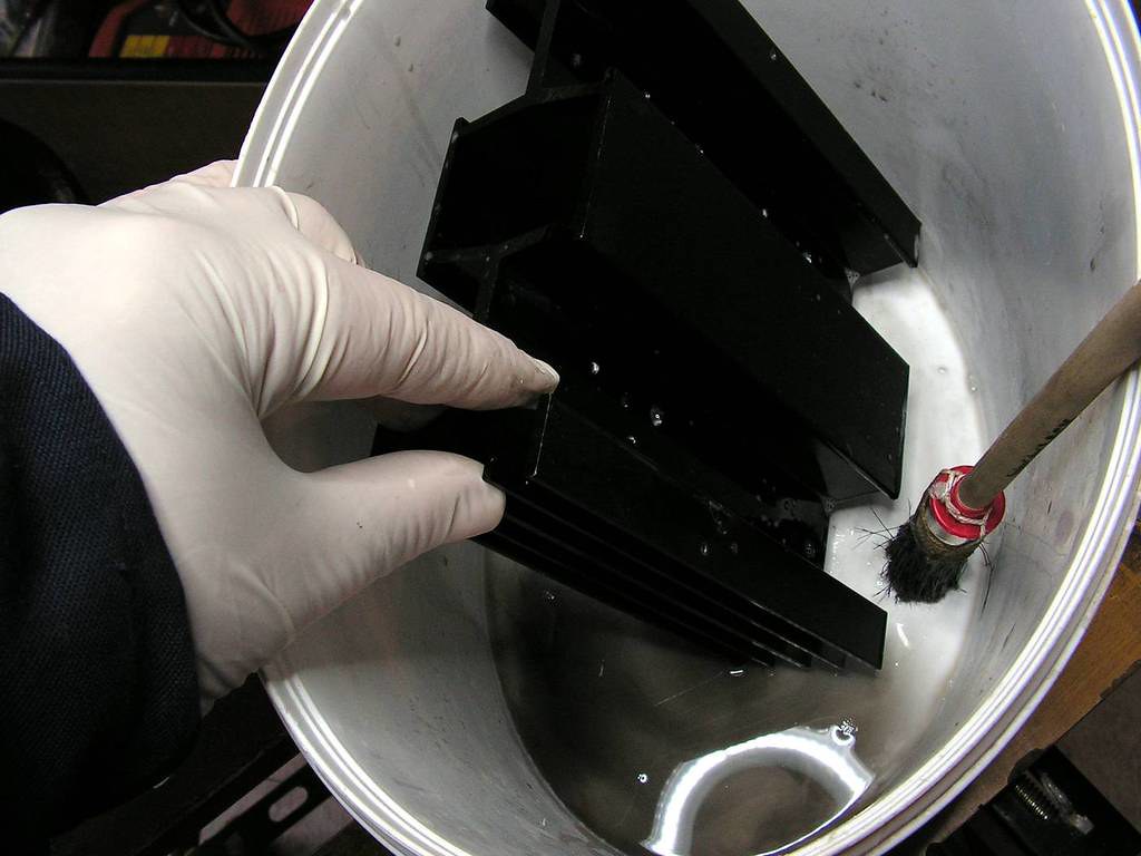
Because of all, a deep cleaning should be done!
And one channel is done! Still without power transistors, because I must clean them all…
The same thing for another channel….
I really don't know why someone did that????
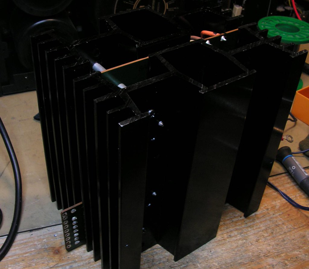
And finally… heat sinks cleaned, boards resoldered, new layer of colophony…. Ready to put back together…
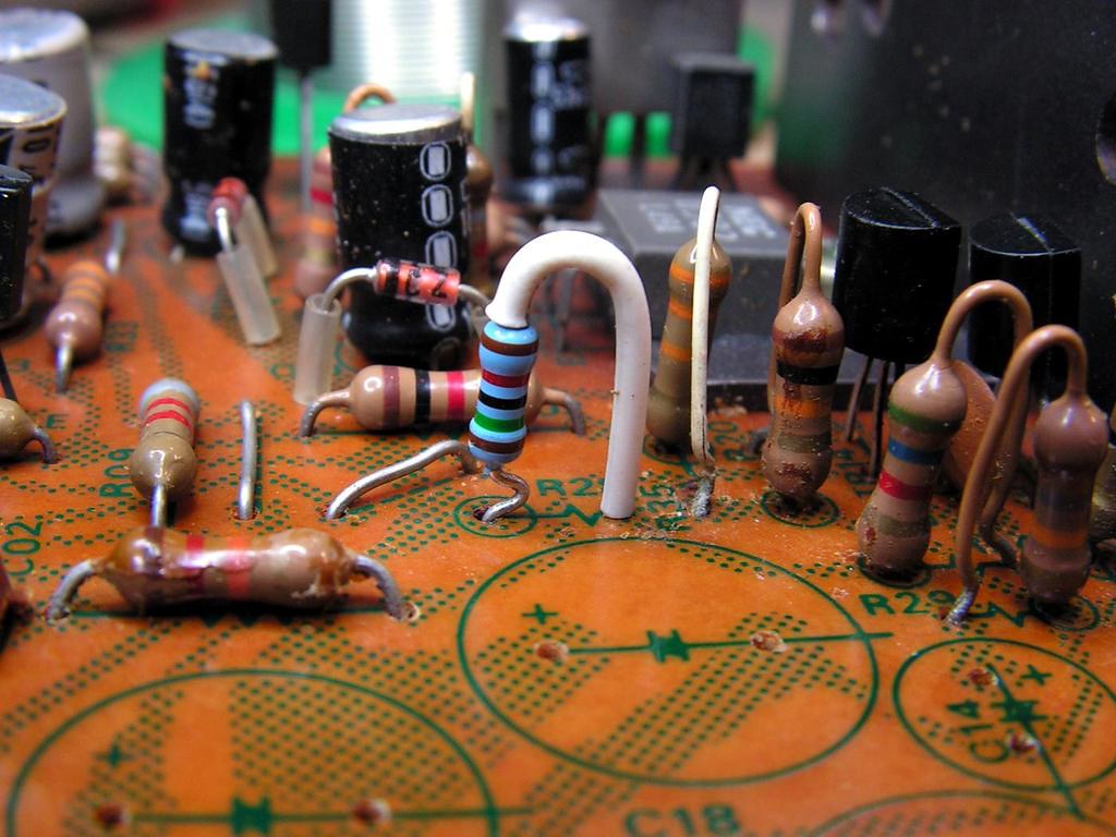
Again that detail with BIAS transistor, now more clear photo….
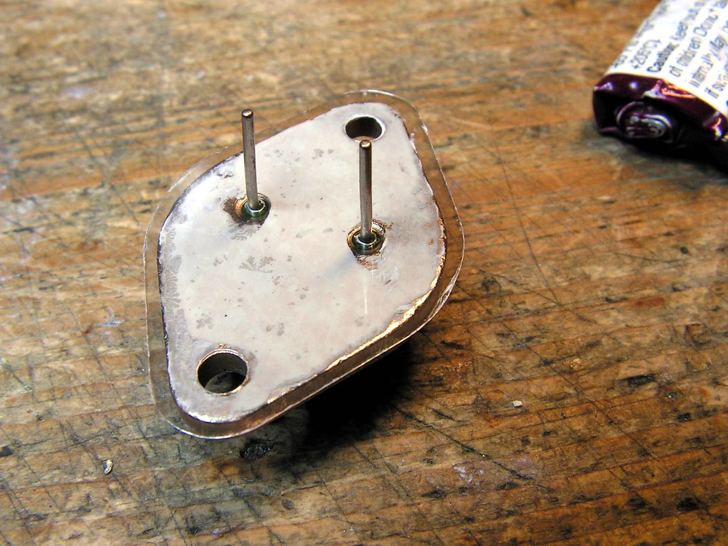
New layer of thermal grease, just enough!
New MICA insulator…
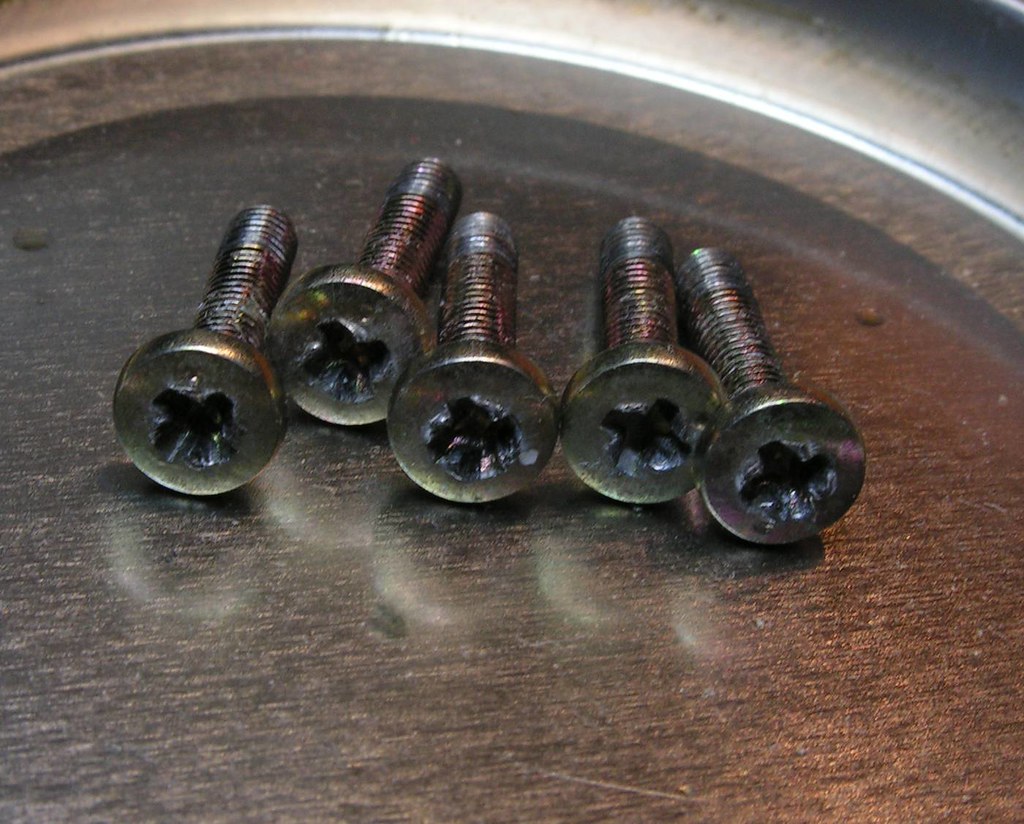
Damaged screws (replaced with new ones made of INOX)
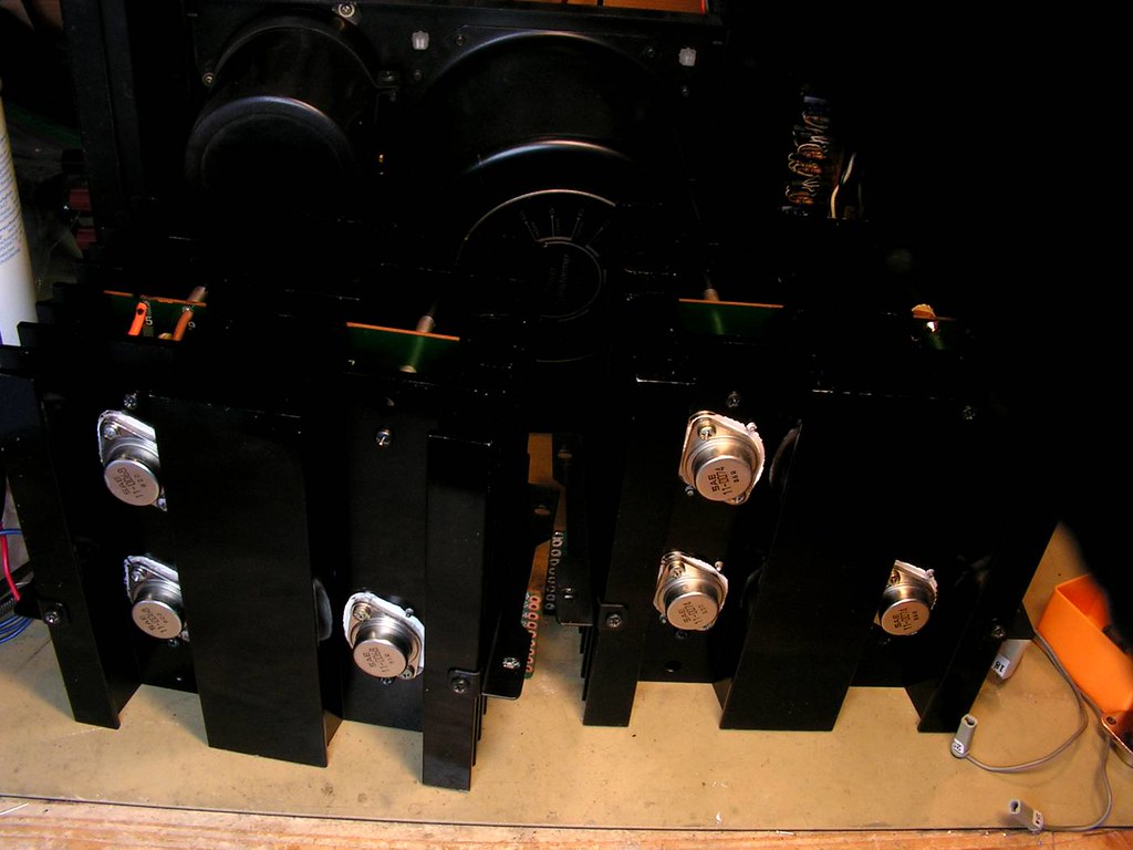
And finally the power stage modules finished…
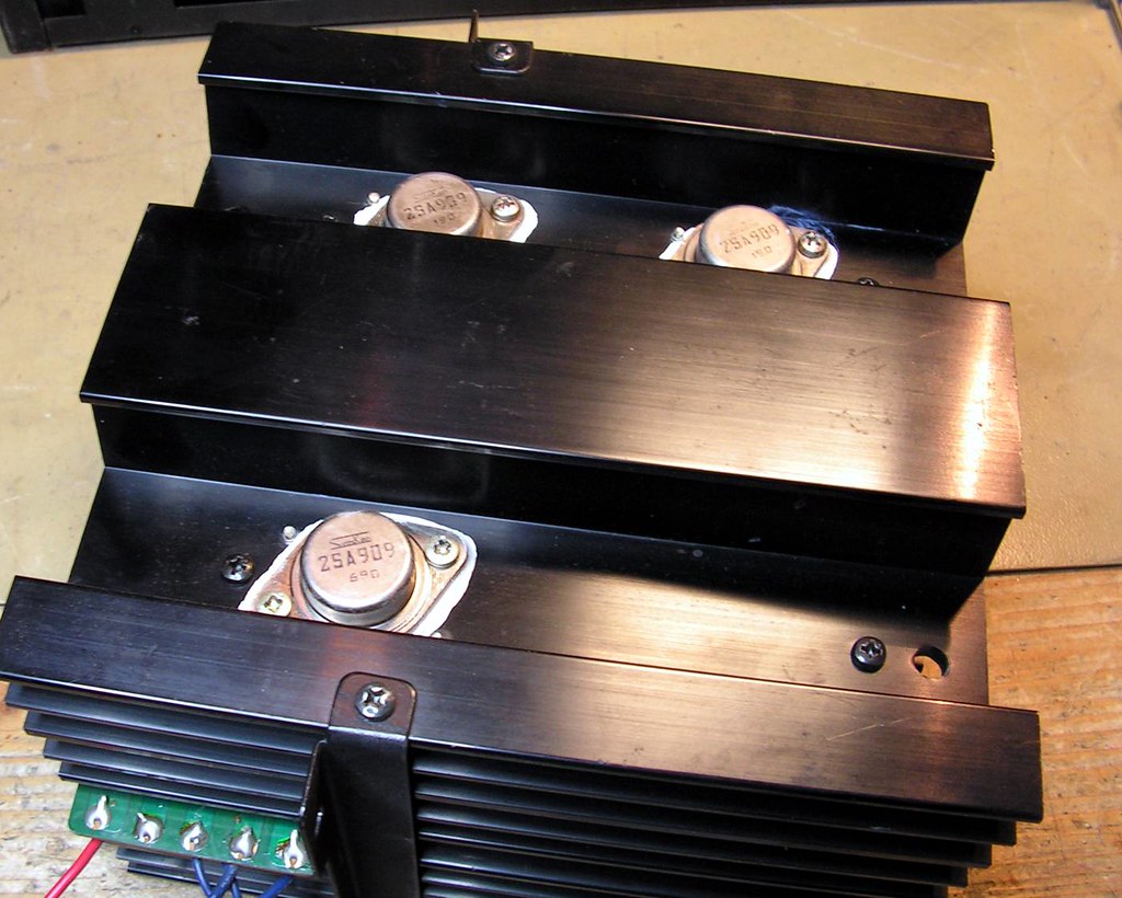
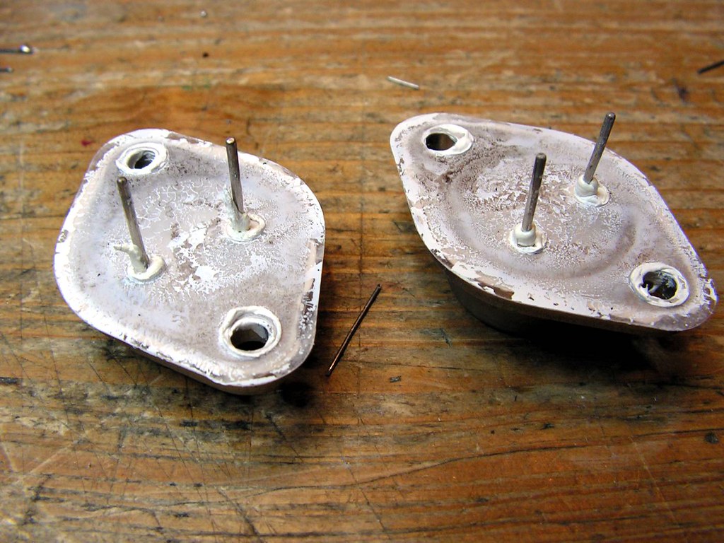
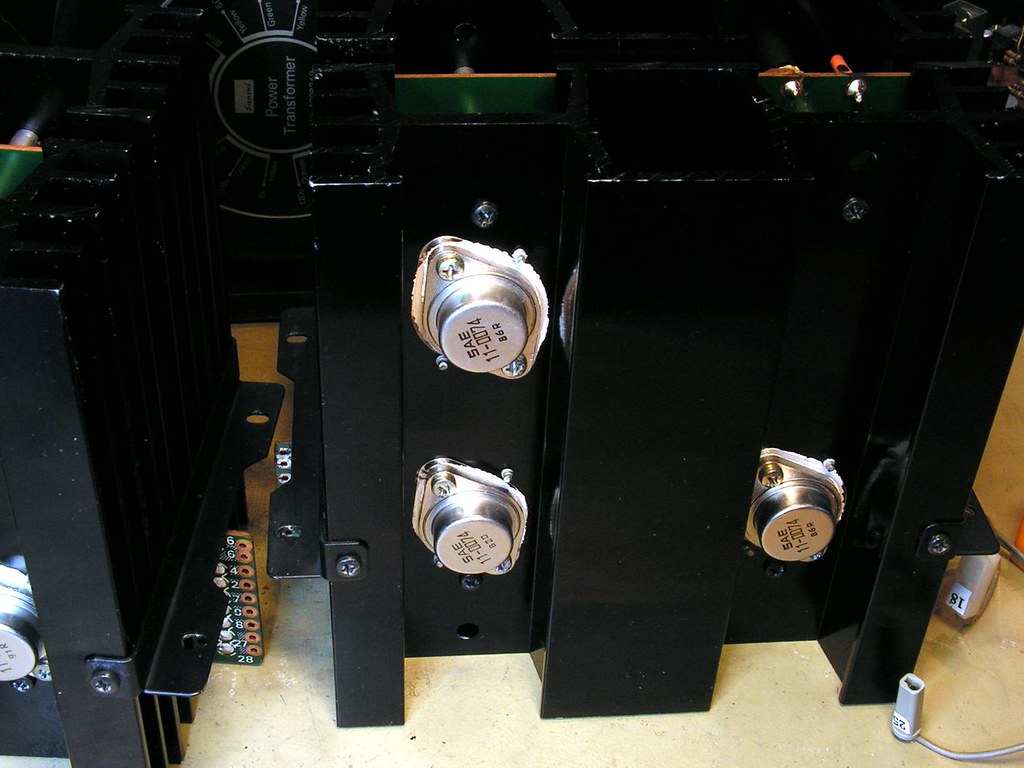
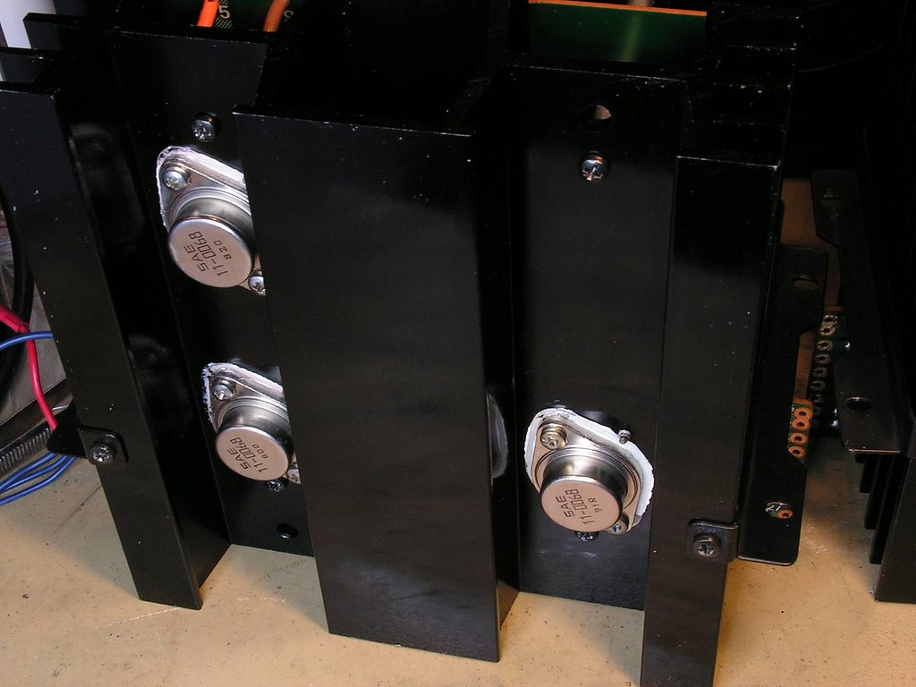
Here, as you can see, I have installed new TO3 transistors SAE 11-0074 and 11-0068. Old power TO3 transistors have very different hfe. OK that measure I have done by my semiconductors tester which is good for small power transistors, but again, some of old power transistor had hfe just only 7 or 9!!
So I decided to replace them all by this SAE combination. Why I chose them, because they are made by Sanken 100% for sure, and I am sure that they are Sanken 2SA909 and 2SC1586 (I gave to test them to one gentleman who has Curve Tracer).
Why I didn’t install Sanken 2SA909 – 2SC1586…. The answer is: the price.
Now we are going to the front side of amplifier
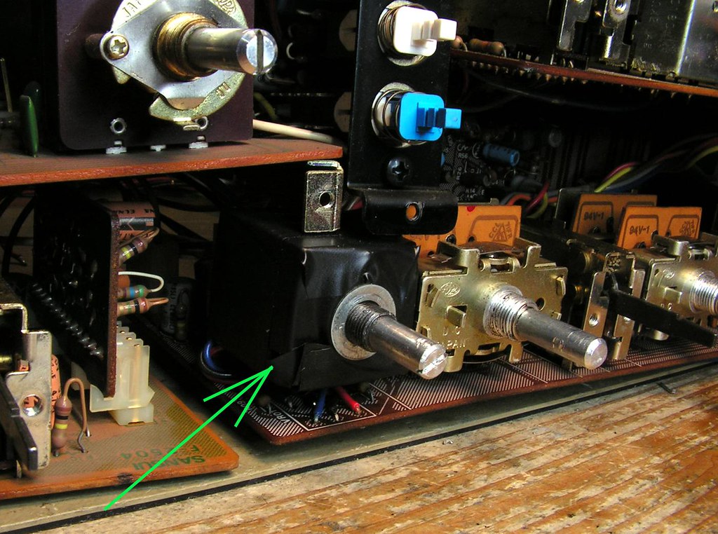
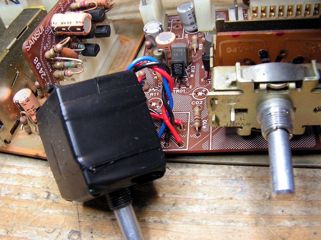
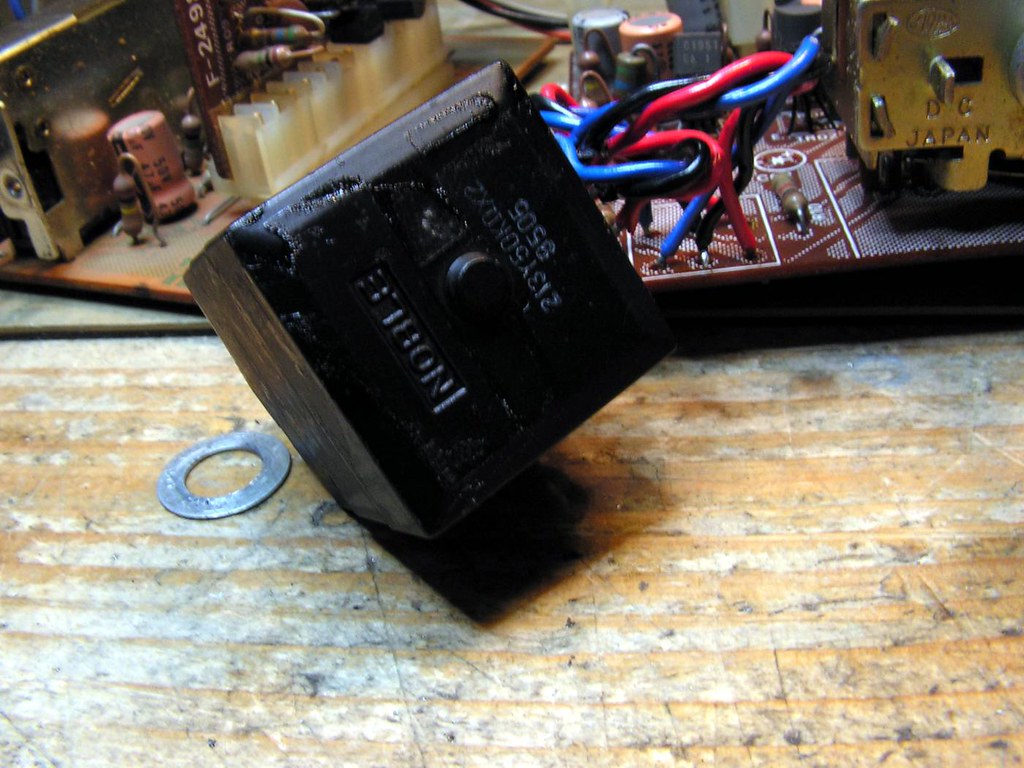
… and I noticed that balance potentiometer is not ALPS…
… it is NOBLE, very good quality potentiometer, but I would install a genuine ALPS balance potentiometer with center click
… and what about that ceramic power resistor beside power meter?
… someone changed the bulbs with lower voltage type, and he installed that ceramic resistor to get voltage drop for those new bulbs. That would be removed too….
… and the current state of amplifier…
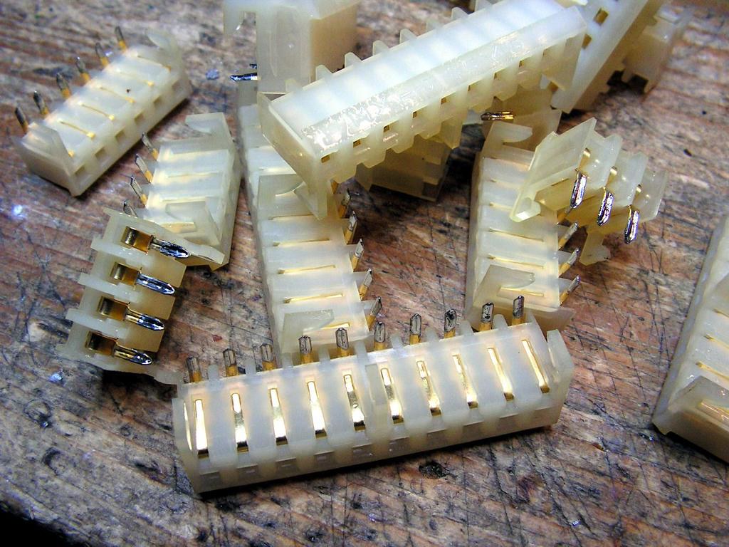
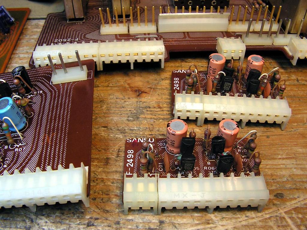
– Cleaning those female MOLEX connectors…
It is very important to get a good contact between those MOLEX connectors, because in AU20000 you have so many boards connected by those MOLEX connectors. While male connectors can be cleaned without problems, female connectors should be removed from the board to get them cleaned.
Below these female Molex connectors is a paper adhesive tape, which also must be removed.
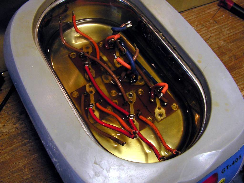
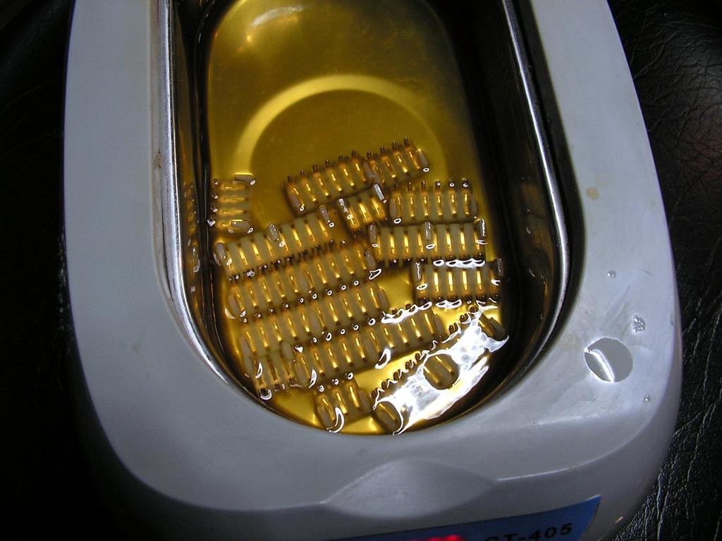
It is the best to clean those connectors by ultrasonic cleaner…
… cleaned …
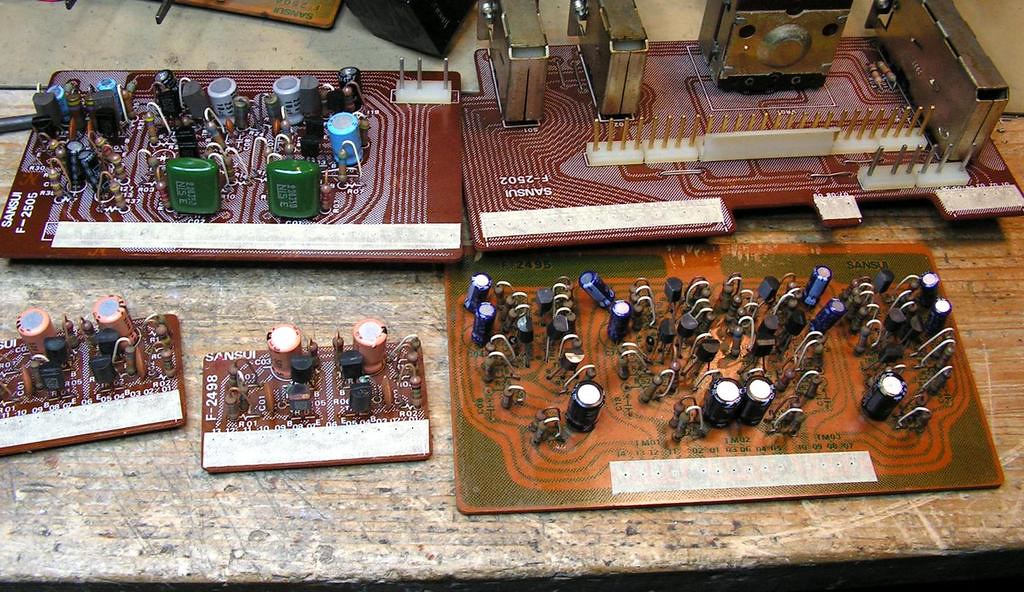
… a new paper adhesive tape….
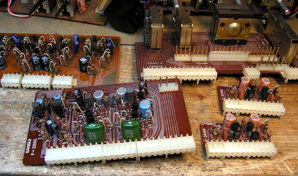
… and connectors are on the boards… now they are like new…
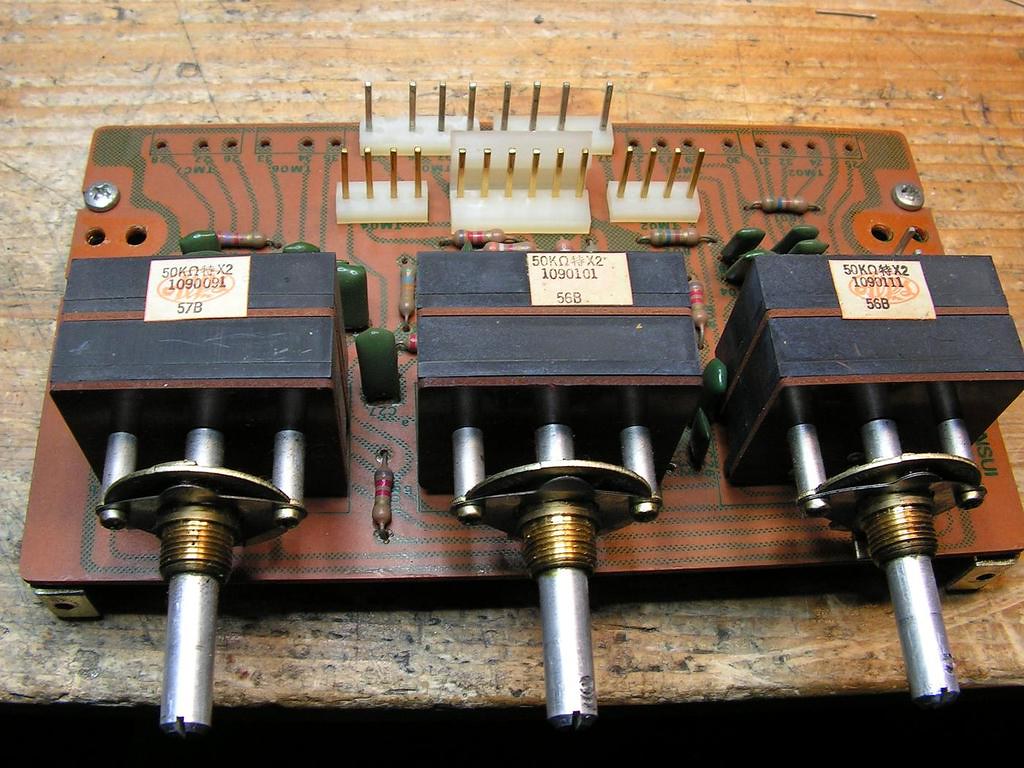
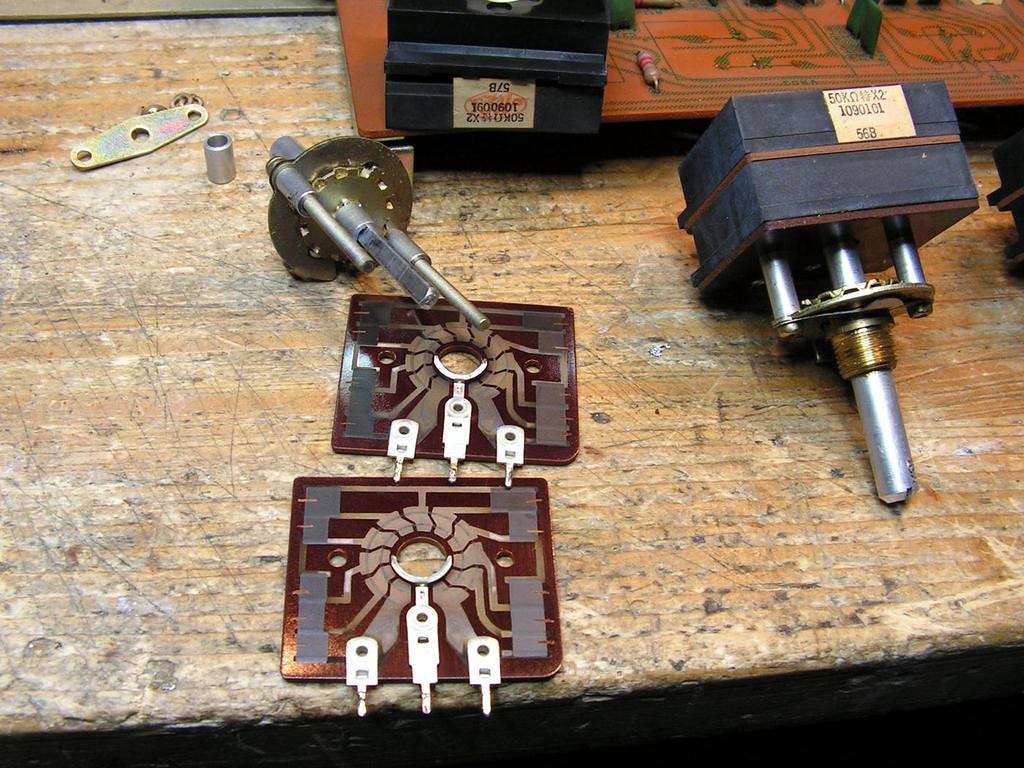
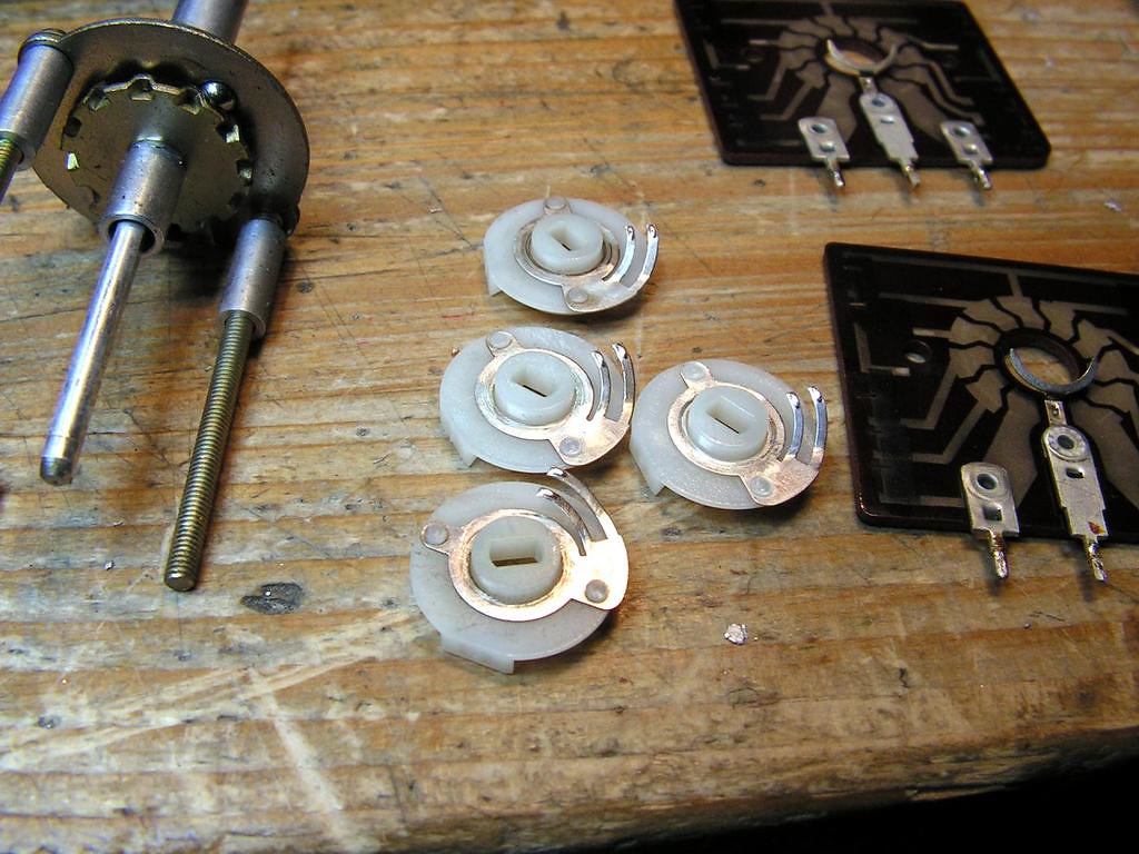
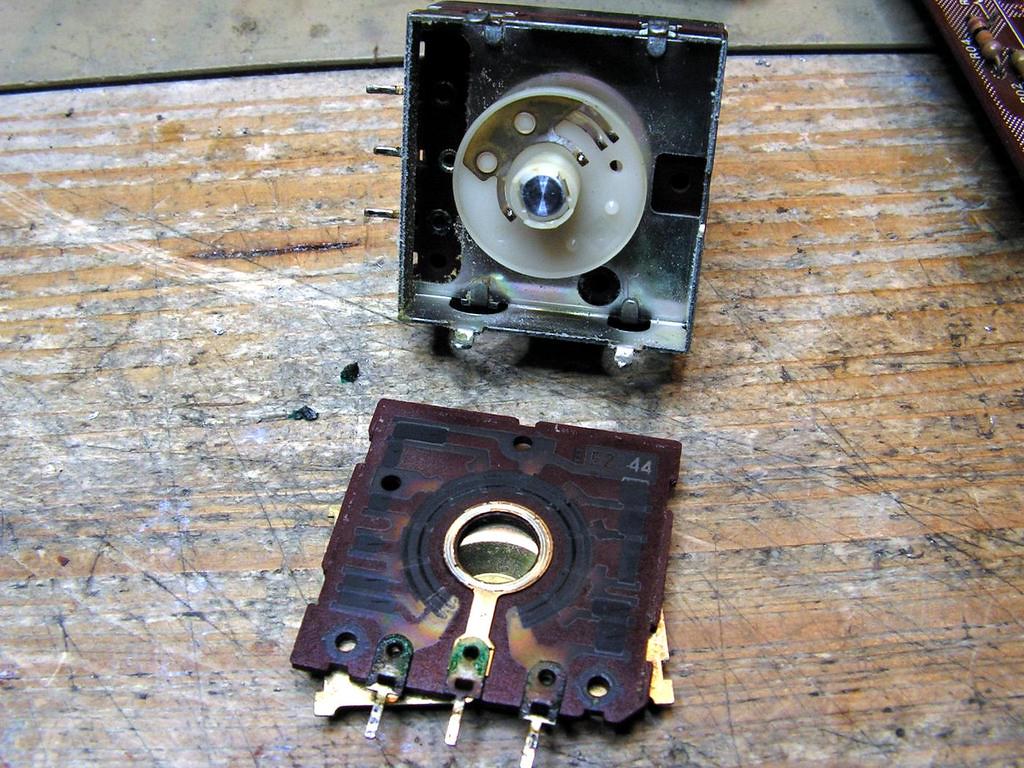
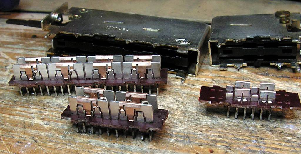
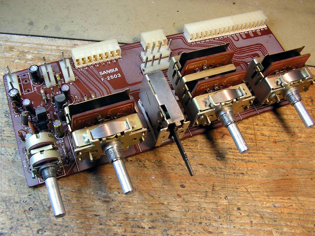
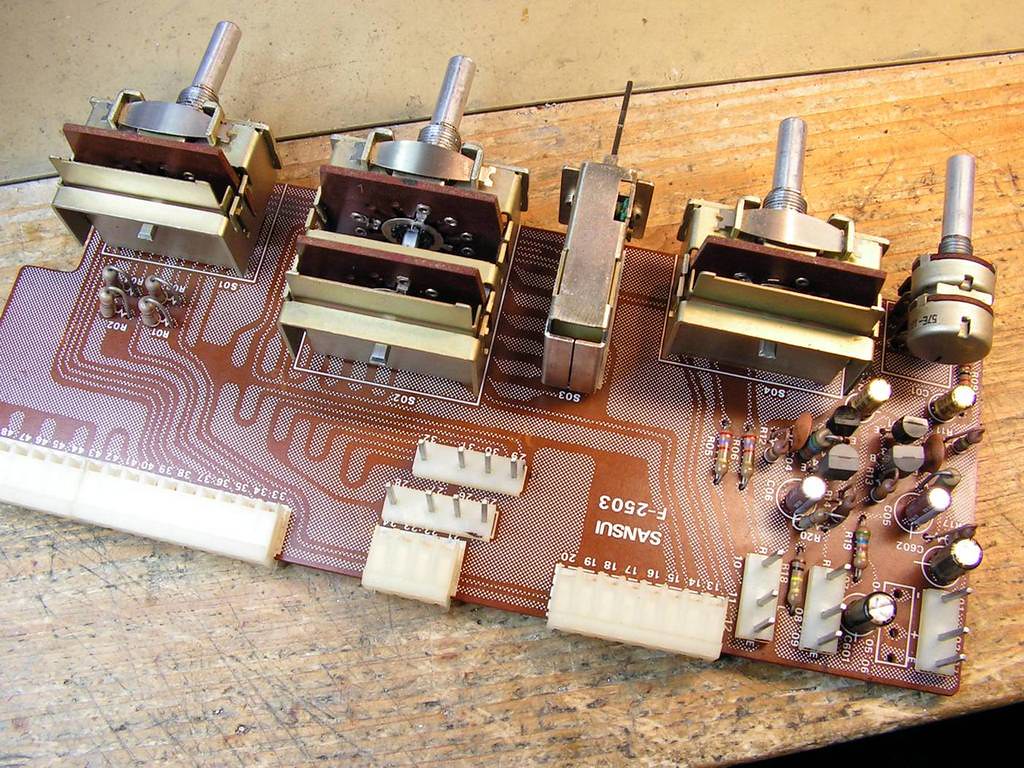
– Cleaning tone control potentiometers….
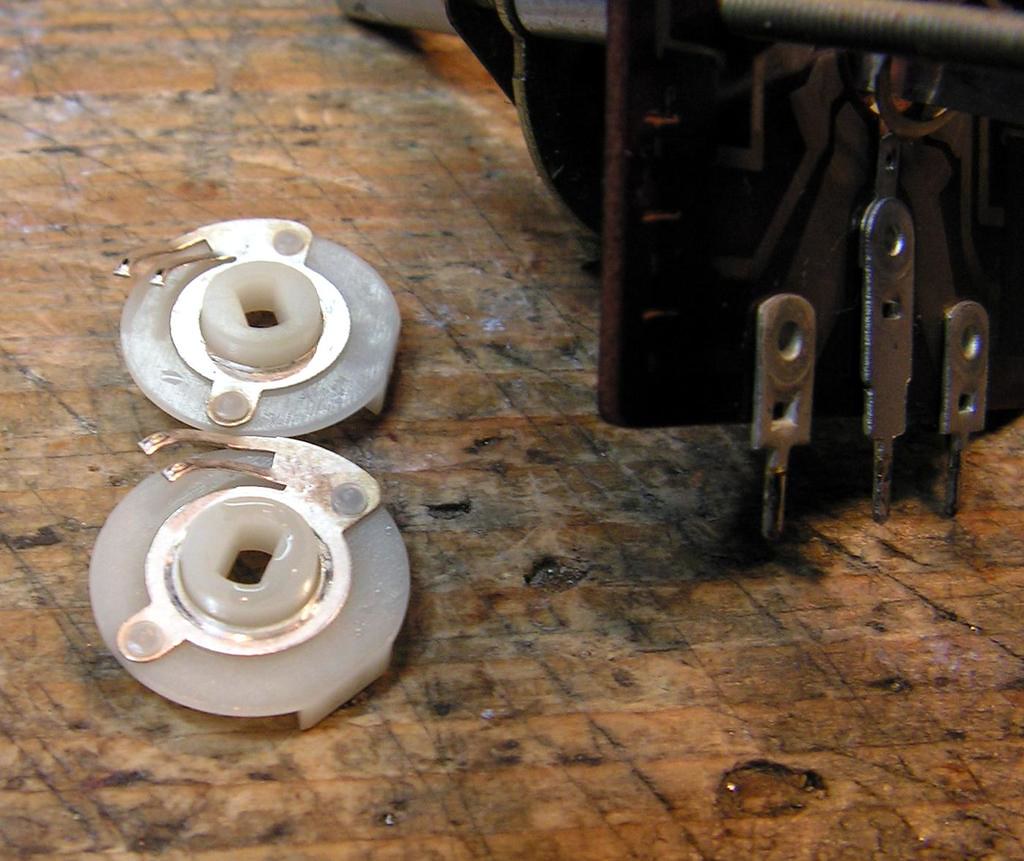
That type of ALPS potentiometers are easy to clean
Potentiometers on this AU20000 was very nice, dry and relative clean…
…. and after cleaning….
Volume potentiometer should be cleaned too…
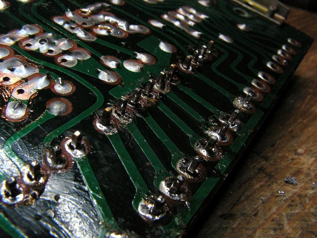
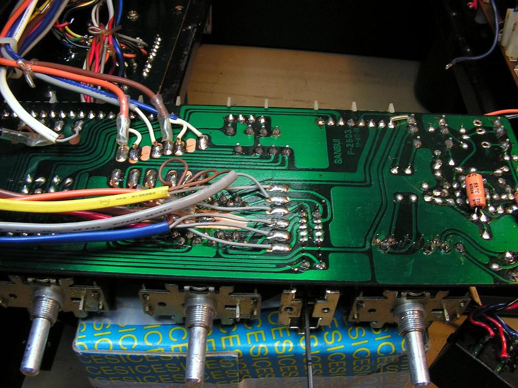
on that volume board, those male MOLEX connectors has very oxidated solder joints, so I decided first to remove those solder joints
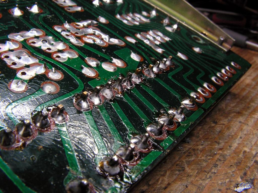
and resolder them again….
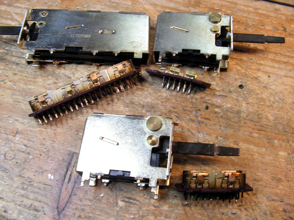
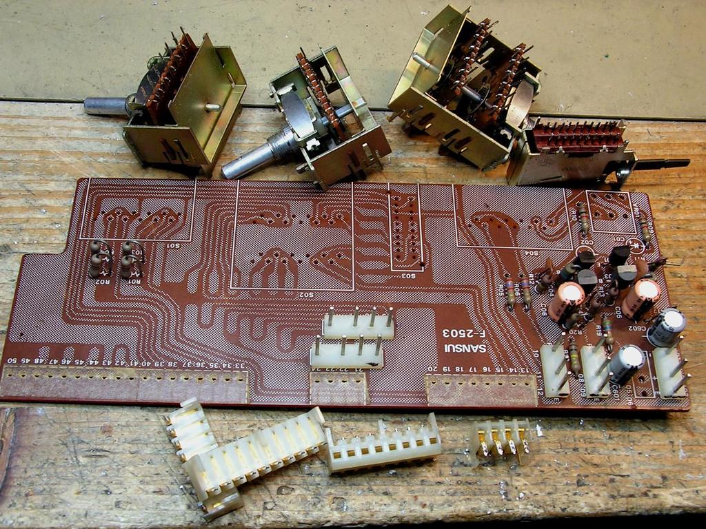
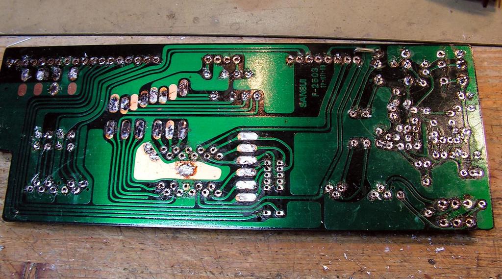
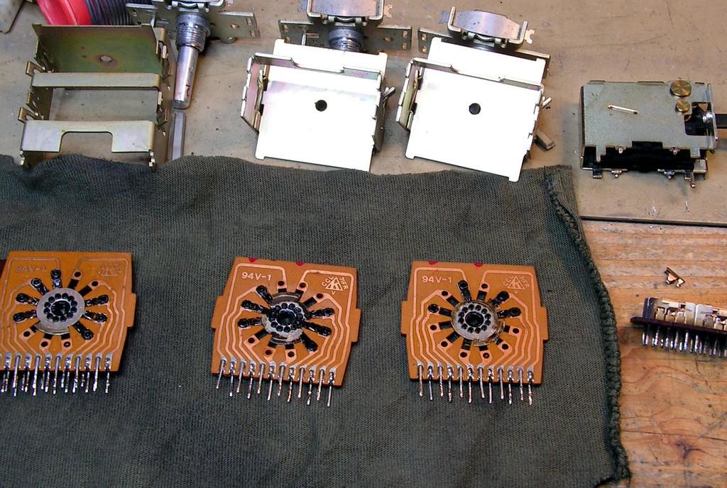
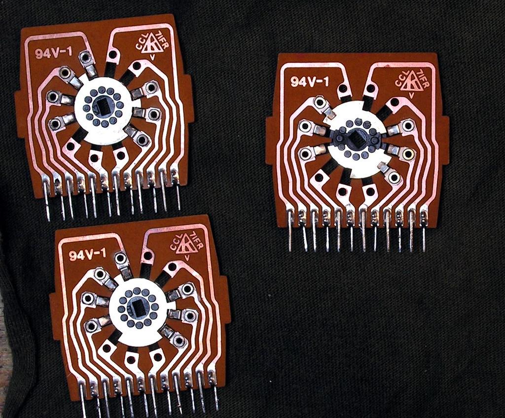
Cleaning those three switches on the same volume board (Muting, Tape-Play and Input Selector)
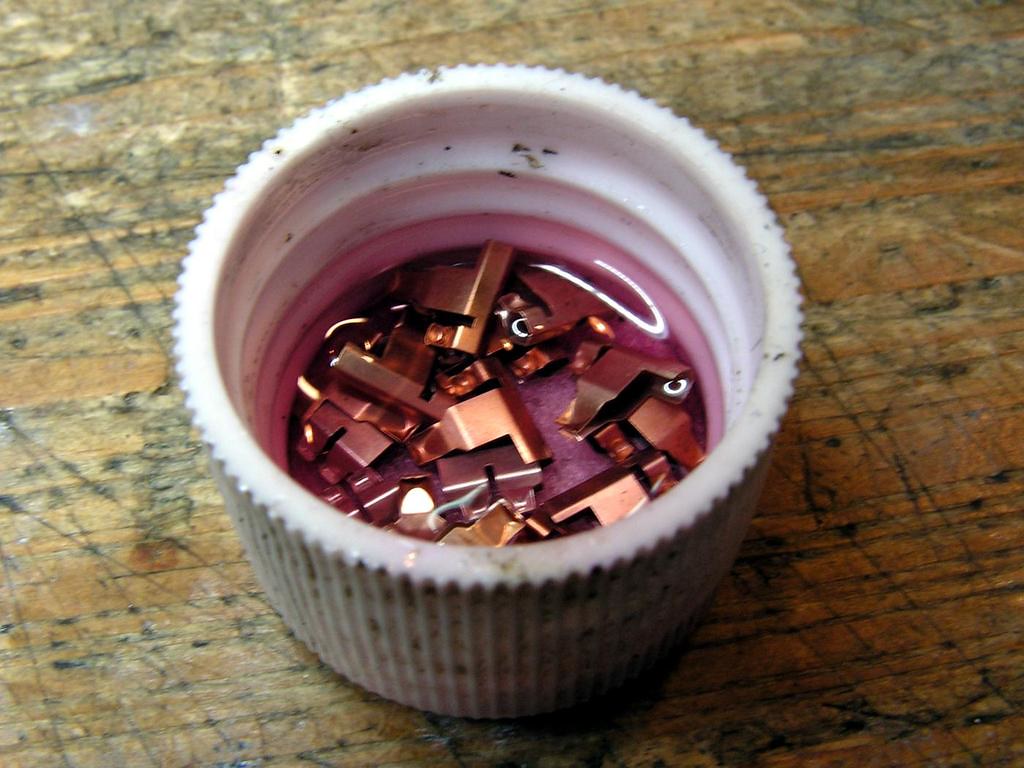
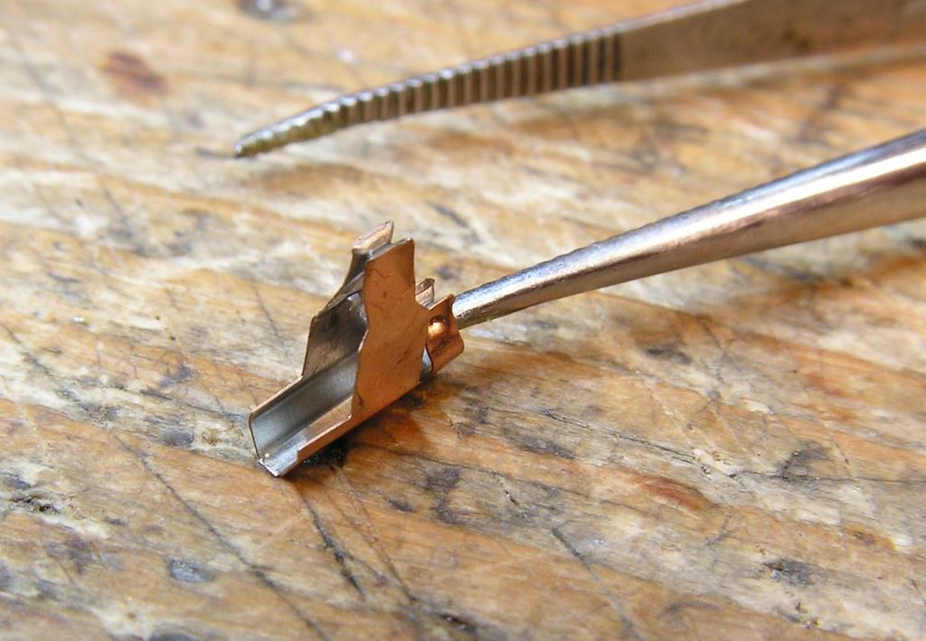
… deoxidation …
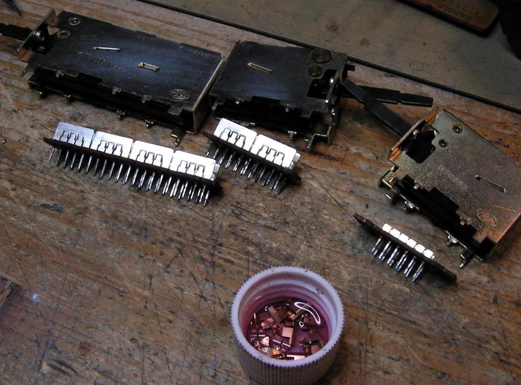
… and how it looks like at the end…
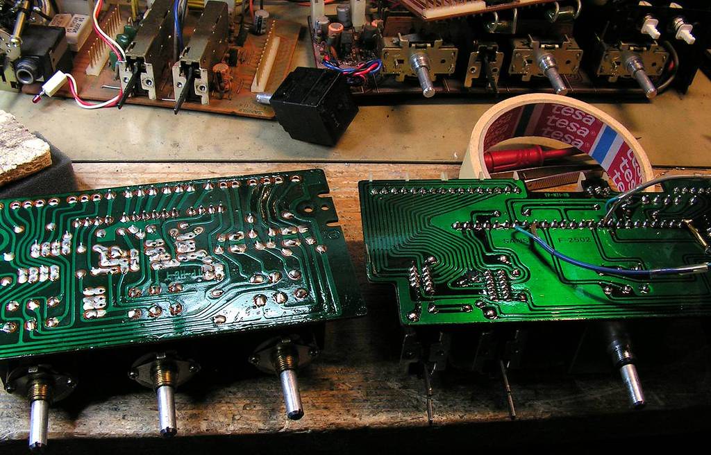
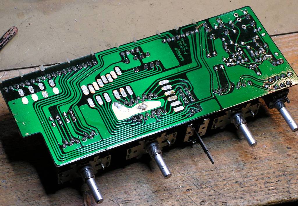
And circuit side of boards, resoldered, cleaned, and with new layer of colophony (rosin)
… the next board… Filter Board…
What needs to be cleaned…
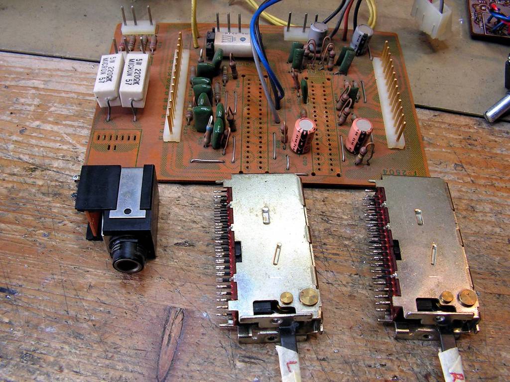
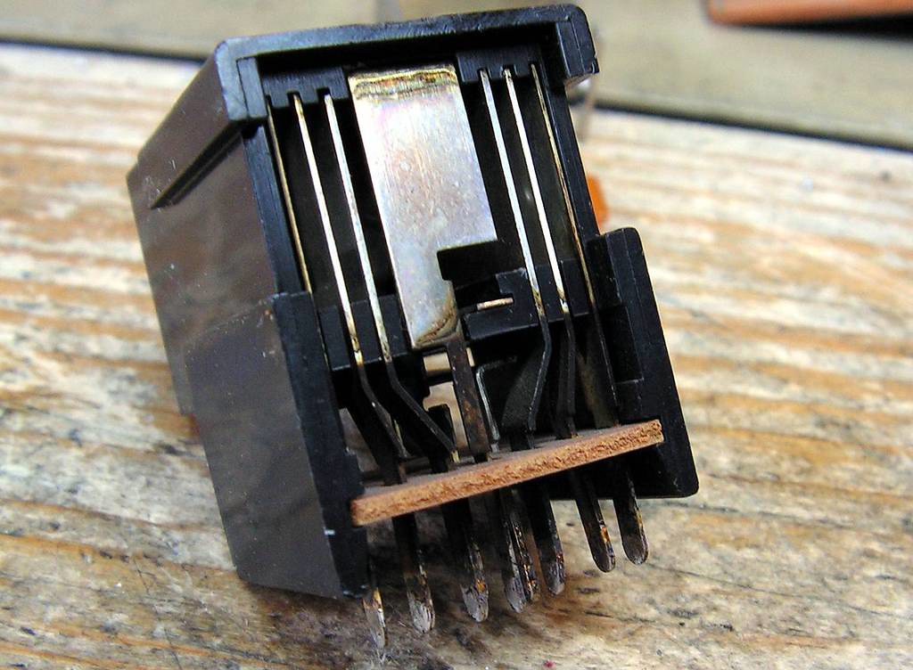
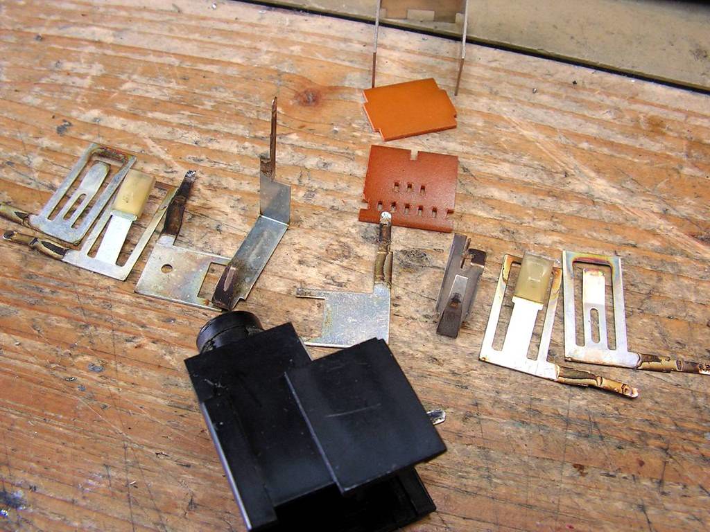
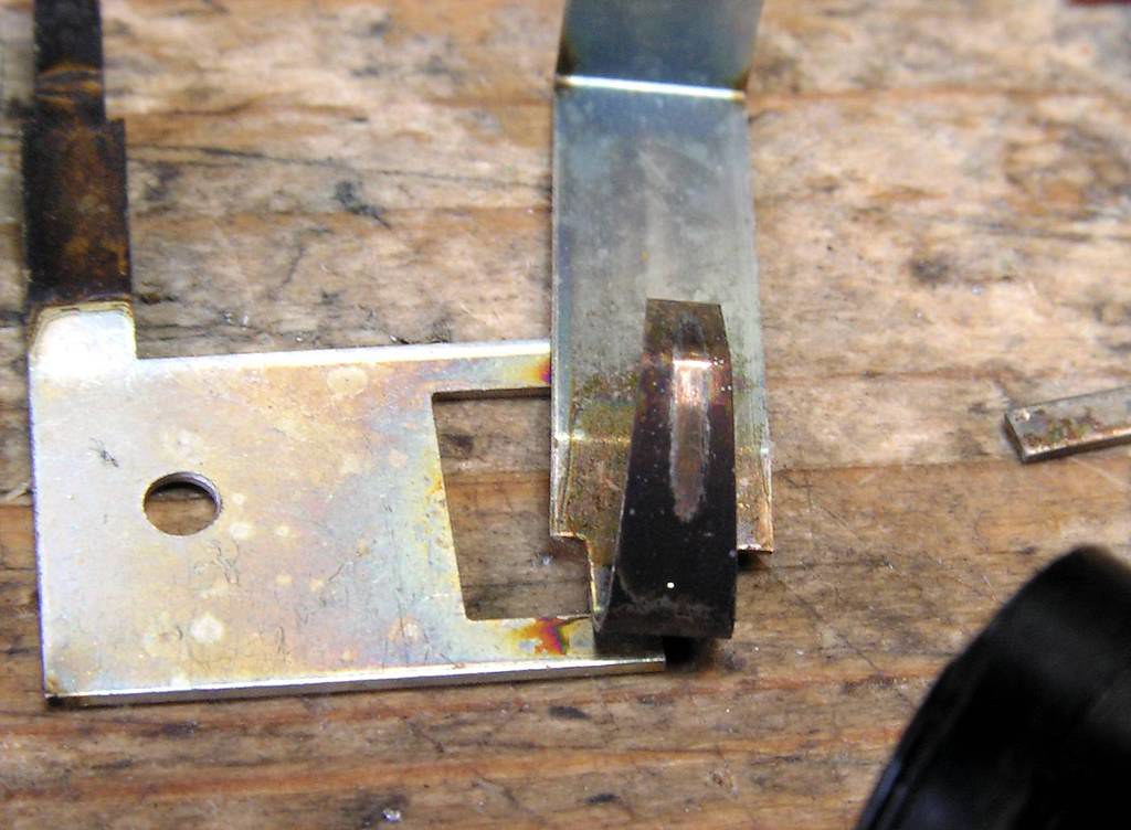
Phones jack too….
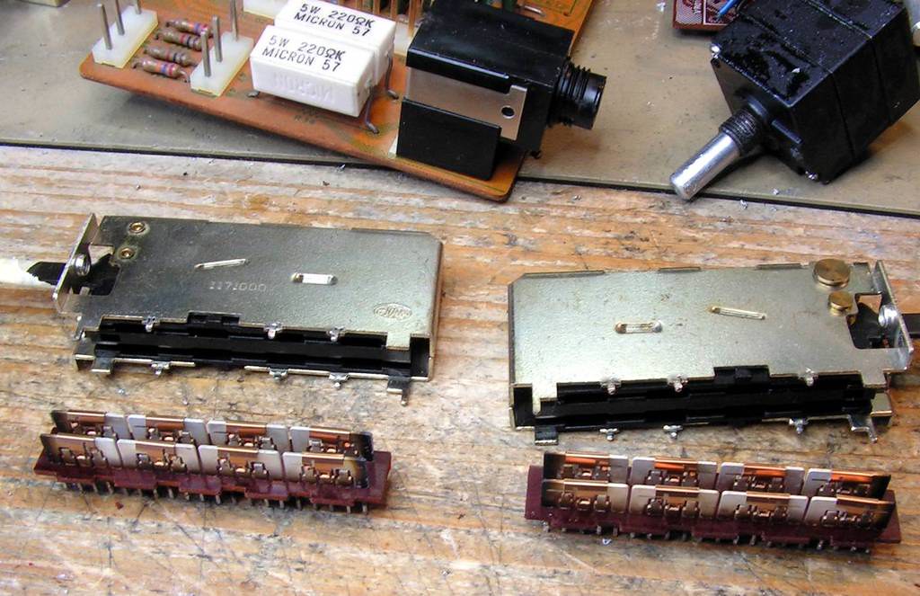
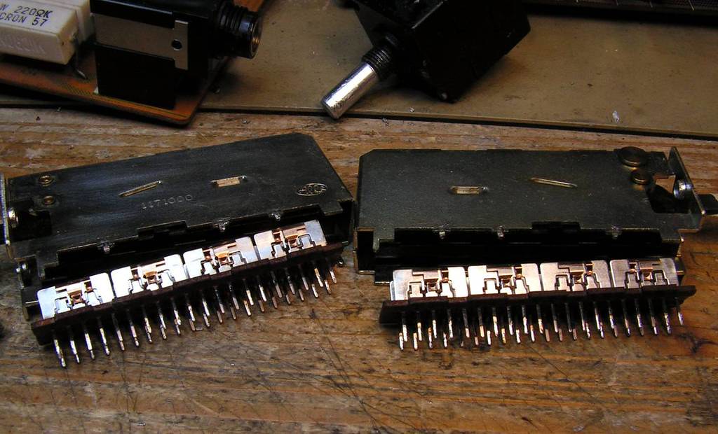
Filter switches before…. (those switched were already clean, but when I opened them already, I cleaned them anyway…)
and cleaned…
The Filer Board finished…
and circuit side…
– The Phono Preamp Board, or like Sansui say… Equalizer Board
For restoring that board I spent so much time… first of all please look how corroded legs have those transistors:
that could be a big problem, especially in phono preamp which is working with low level signals (in uV), sometime that corrosion could enter into body of transistors, and then it can make a lot of trouble!
I replaced them all with Toshiba 2SC2240 / 2SA970 combination.
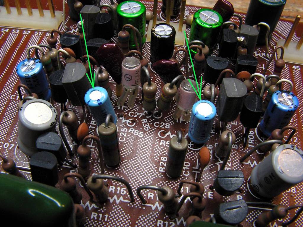
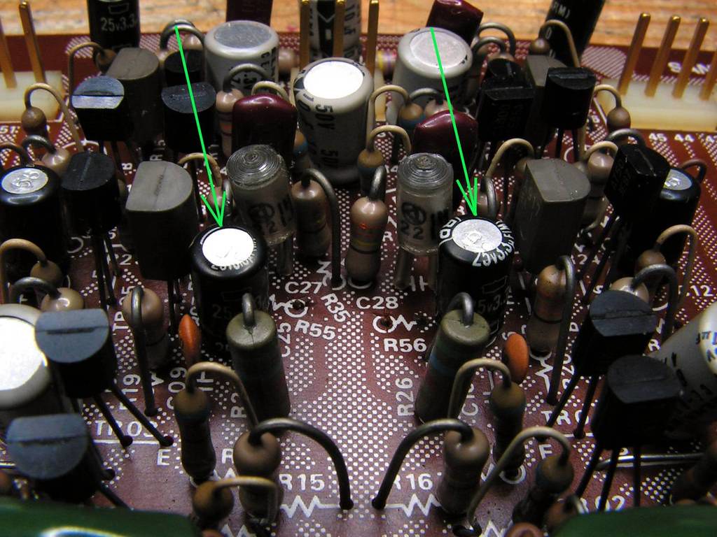
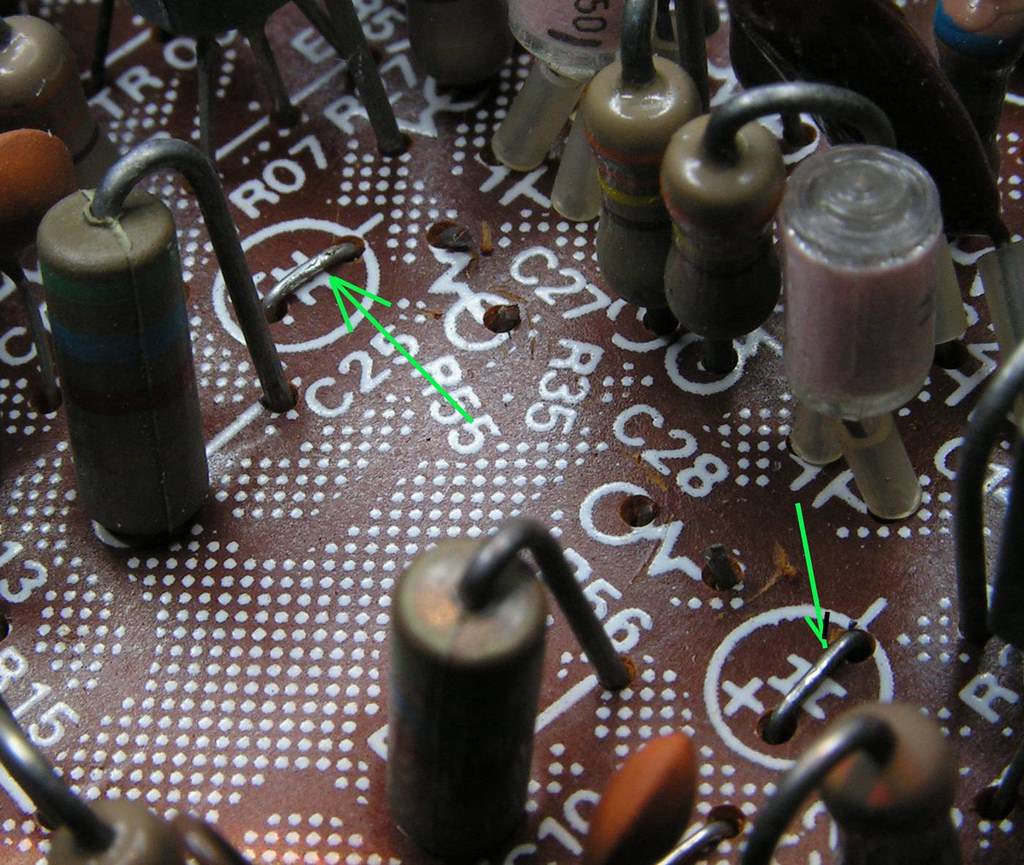
Another problem is Sansui “charm”… I like Sansui sound so much, and Sansui engineers are the best for make a good-sounding-audio equipment, but, in other hand, who can make this kind of error in design?? Extra resistors, cutting printed circuits…
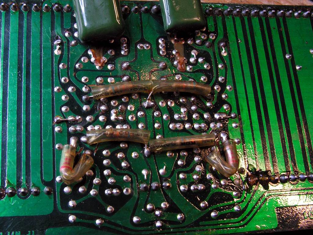
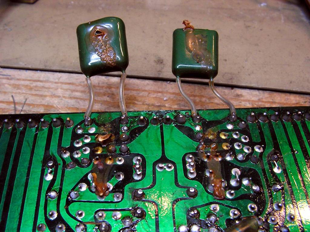
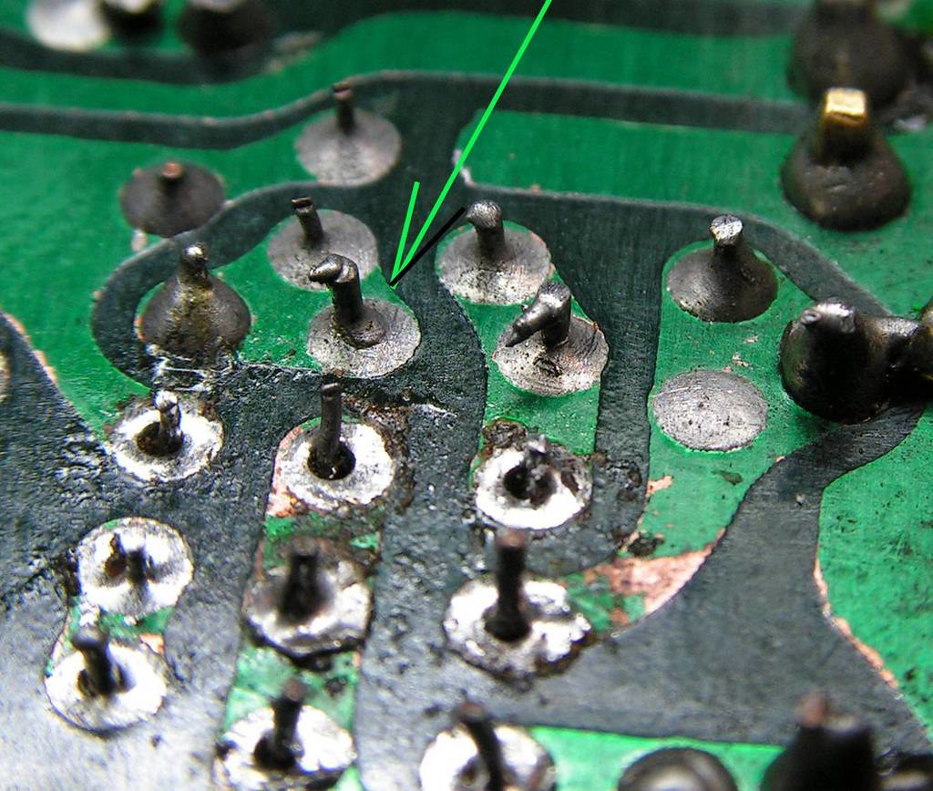
… and what to say about those capacitors?? On circuit side of the board the legs of those capacitors are short-circuited! So why they installed them?? Or why just cutting resistors R55 and R56??
I suspected that someone has modified that, but I have one exactly the same board, and the same things are on that board, so that is something what I cant understand….
So I did that on the right way…
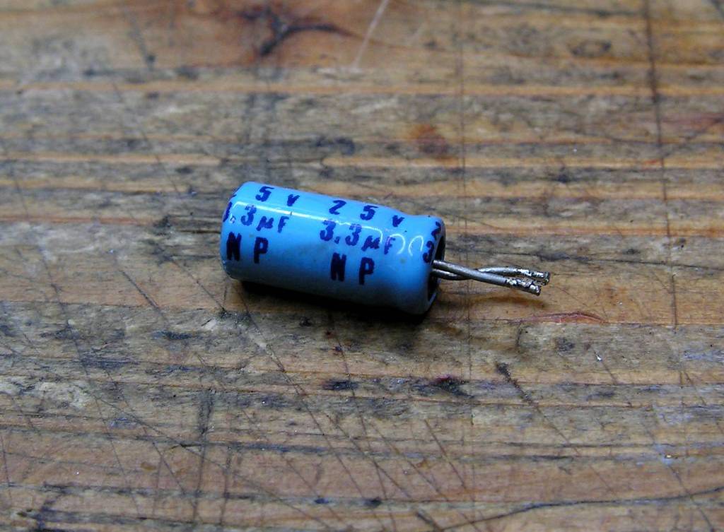
… and just for record, the capacitor what was shorted is 3.3uF bipolar type…
… another problem was this:
You probably know how is a big problem to remove that glue on the element side of board, removing that glue on circuit printed side of the board is twice or even more bigger!!! You should be very careful to not damage a paint (or printed circuit!) but it is very hard to remove that glue…
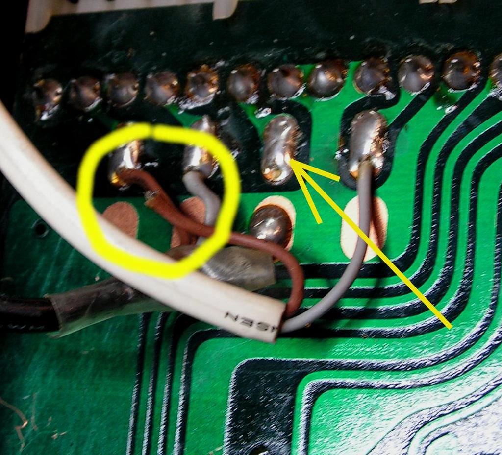
One interesting detail… bad solder joint…
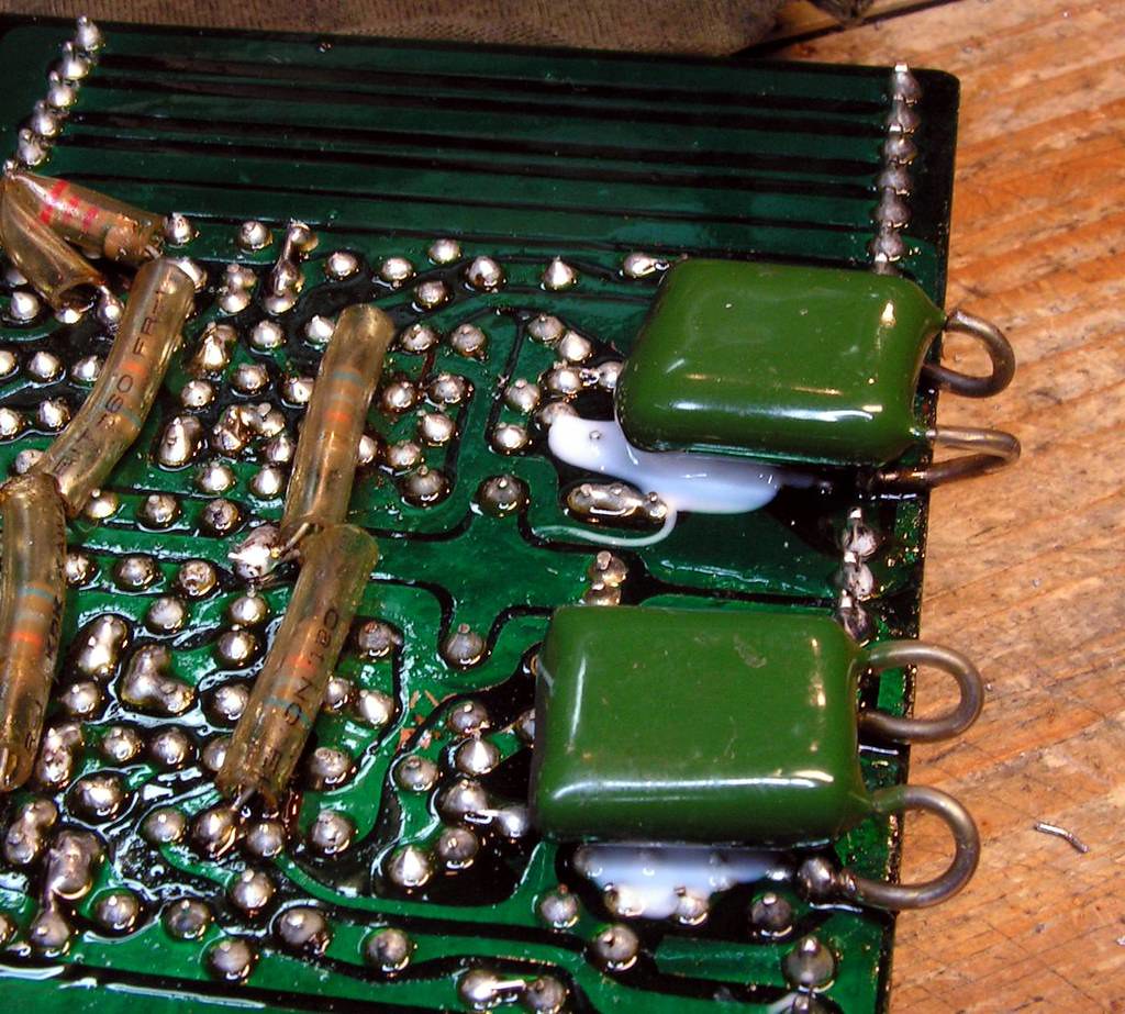
And at the end…. after I removed all old solder joints, resoldered back them all, cleaned compete the board, new layer of colophony, I decided to glue those two foil capacitors with silicone glue just for electronics. It is much better solution, because if you decide to remove it in the future, it can be removed without problem, and the most important thing is what it is not aggressive like Sansui glue…
and at the end…
And now… I know that board will take me a lot of time… The Tape Copy Board…
lot of signal wires, lot of connectors, swithes, selectors… all that should be cleaned
First one interesting detail, during all those years, and because of heat, those signal cables becomes hard, and it is very easy to broke some of these wires, I have found one…
I dont know, was it broken before, or now during dismounting job, but, as I said, you should be careful…
And what it needs to be cleaned…
On the other side, all old solder joints were removed…
Some of wafers, how they were looking, again I would repeat, not so bad, but I would clean them anyway….
How they are now…
and new tape…
Complete board assembled… with genuine BALANCE potentiometer
And now…. – Regulated Power Supply Board…
That board has four regulated power supplies: +/- 65V and +/- 35V
The board has one damage, but someone already fixed that…
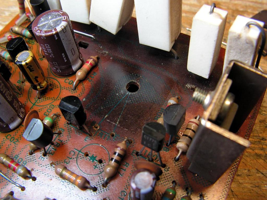
Again, the main problem here is overheating…
it seems to me that heatsink for TR11 is insufficient, look how dark is the board because of overheating….
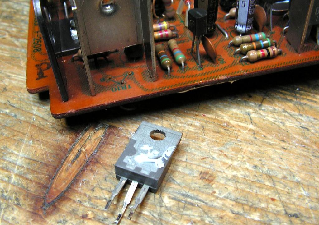
You know that I am trying to keep semiconductors from that time whenever I can, I think that NEC combination 2SD382 / 2SB536 is very good as driver transistors, but here, I think that 2SD382 is not good, so I replaced the both 2SD382 with Motorola MJE15032.
TR05 and TR10 (2SD381) I kept, just replaced old thermal compound on them with artic silver thermal compound.
And classic problem… Sansui glue….
because of glue, I replaced that resistor with new one…
finally clean board…
I already wrote how is important connection between the nut, board and tab of the transistor (collector), so every time the nut I soldered directly to the board.
… again, new paper tape….
… and connector….
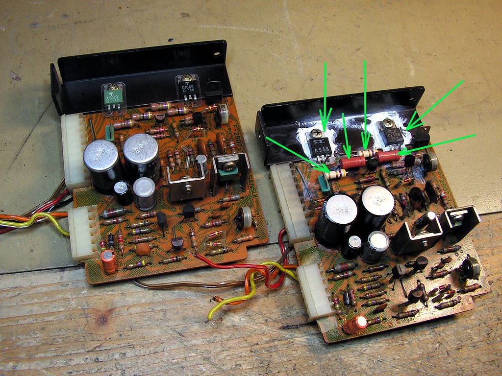
So, what I have changed on this board
Finally, a new layer of colophony
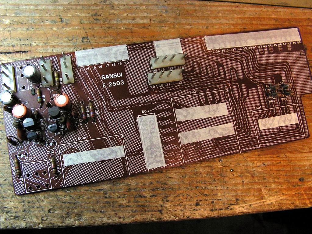
The next board is – Tone Amplifier ….
Please look at that damage
That is because someone in the past tried to pull out that board with pliers!! What to say….
As I said at the beginning of this thread, that is only one board on which someone did some ki
