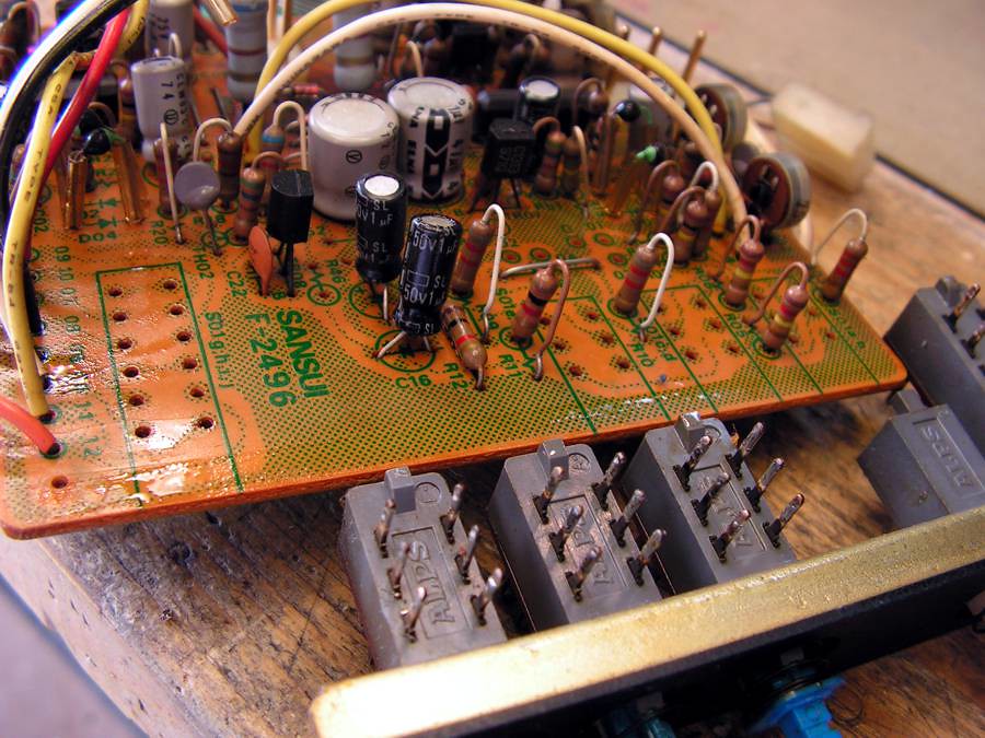
Restoration of Sansui AU20000
Here, I would like to show you one the most interesting restoration what I have done those years…
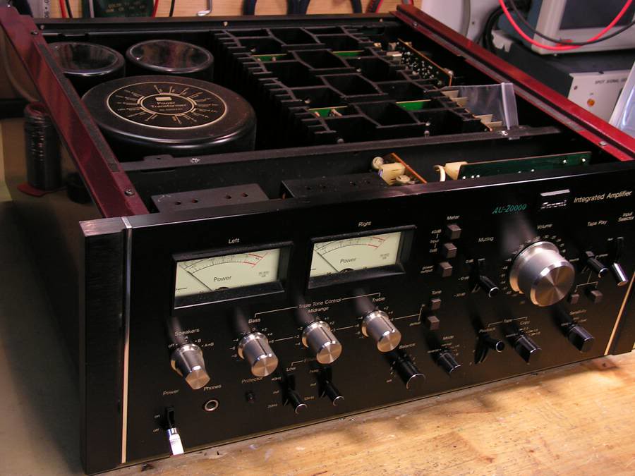
This is the first picture, about what amplifier I am talking here
It is really nice amplifier, but it has a problem, it stays in protection mode…
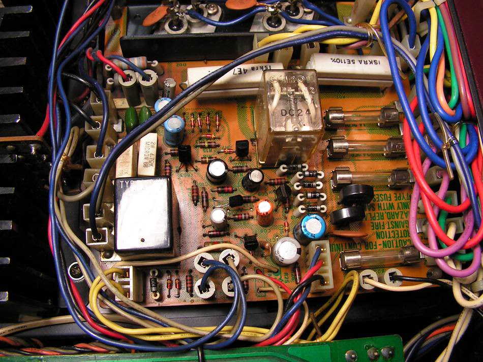
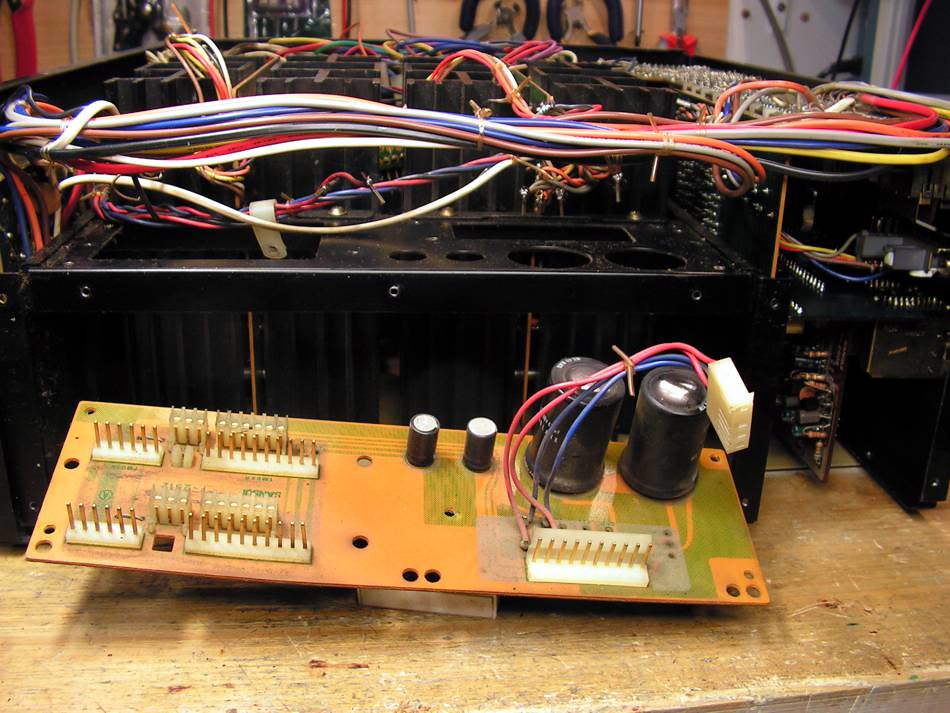
So my restoration has started with this board:
This is a board where is the main rectifier and where is protection circuit
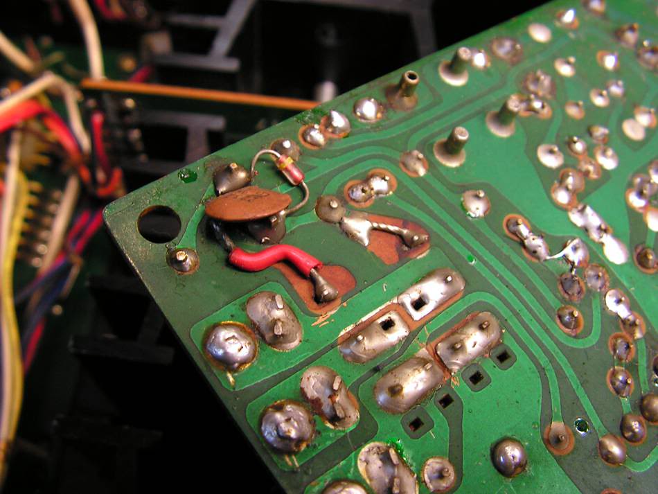
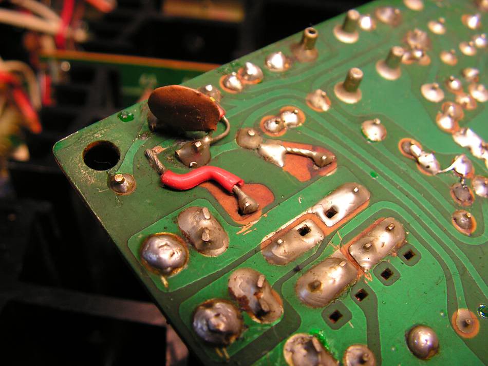
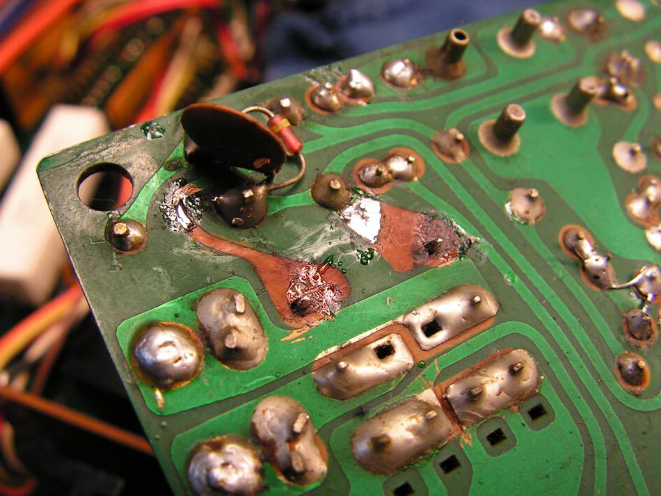
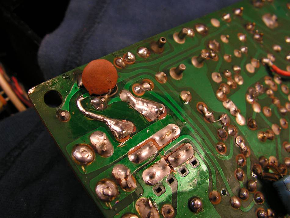
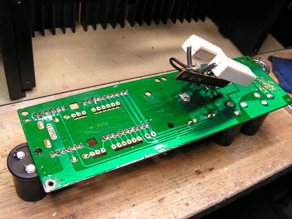
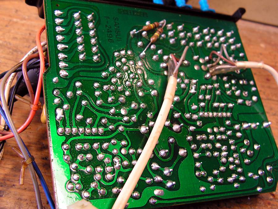
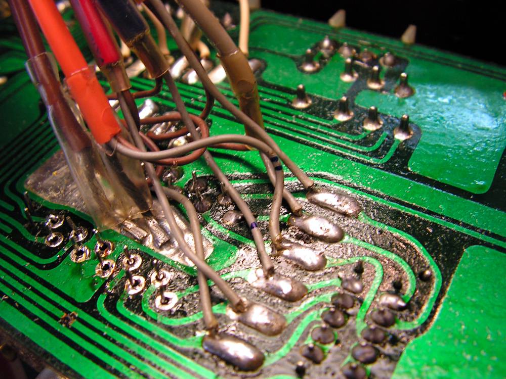
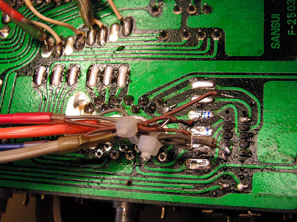
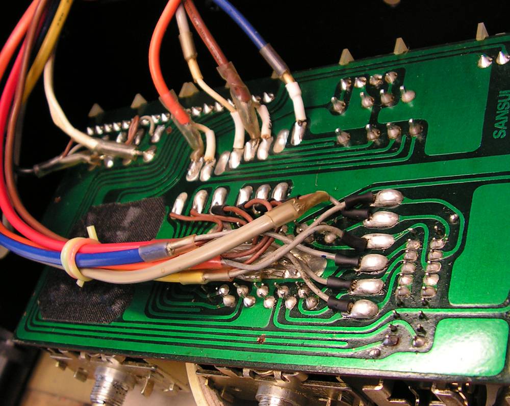
But at other side of that board, I have found some job from someone in the past, and that job was not nice
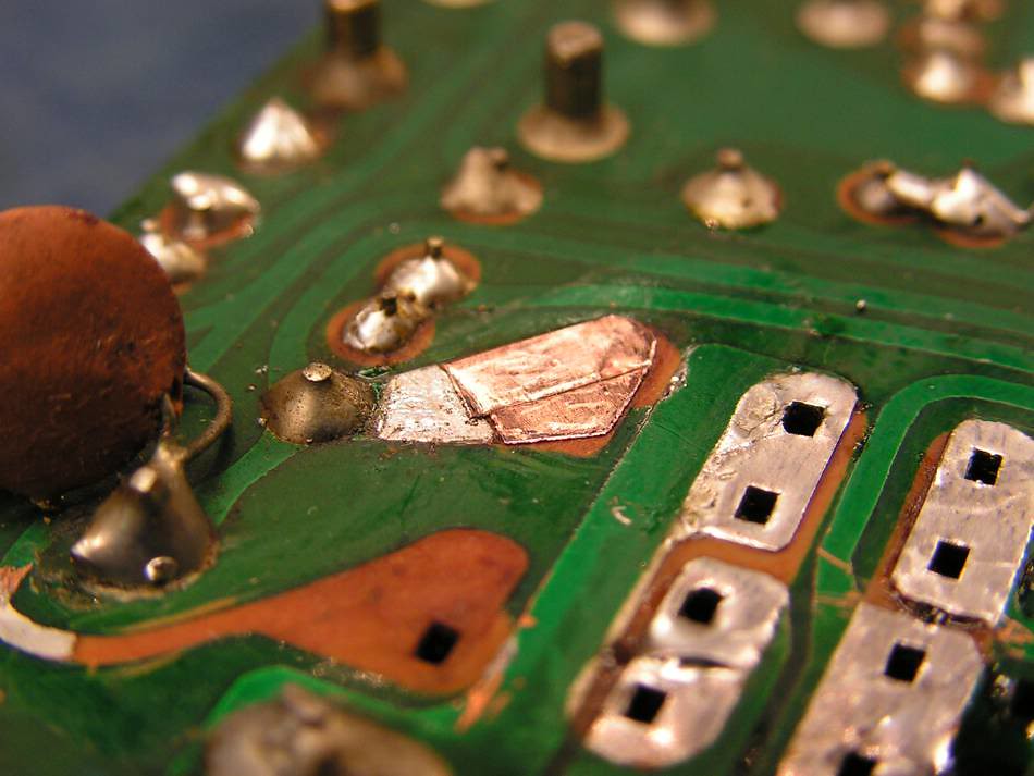
So I decided to make one "face lifting" on that board
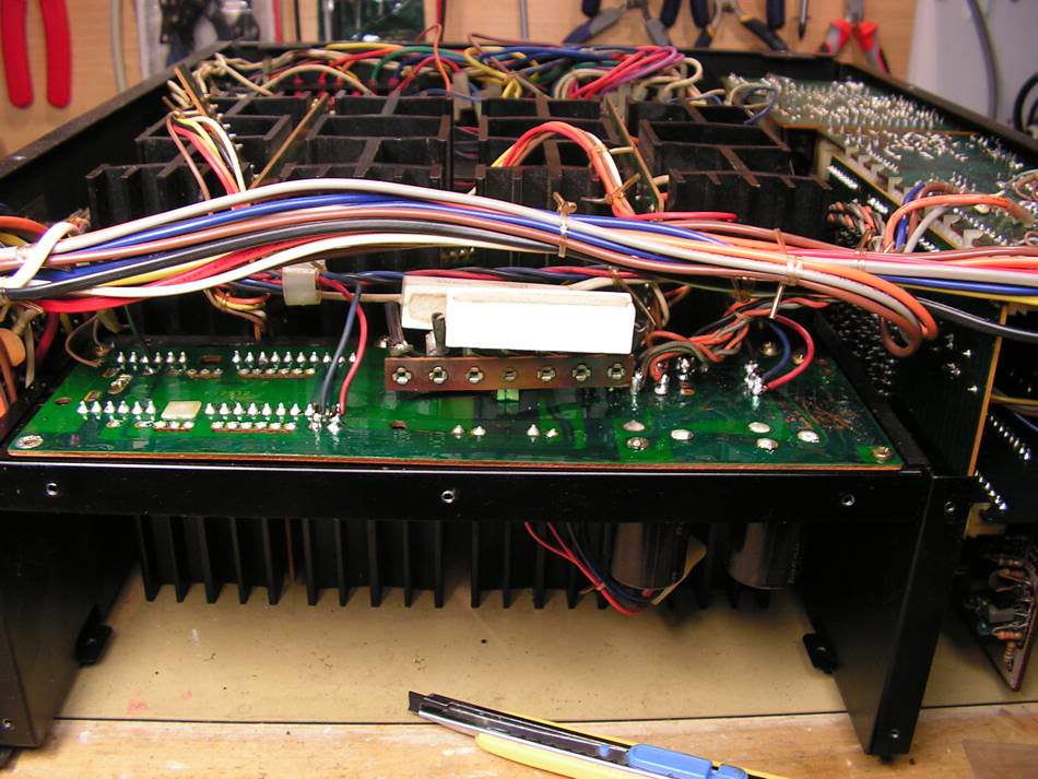
and the result is
… but it was not only one problem…
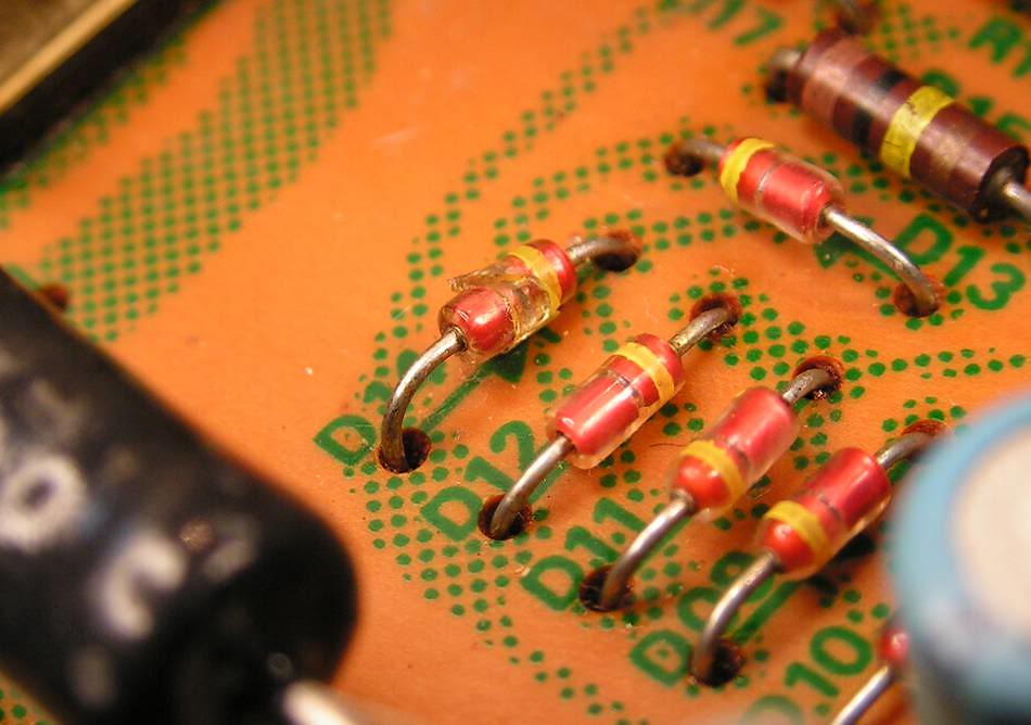
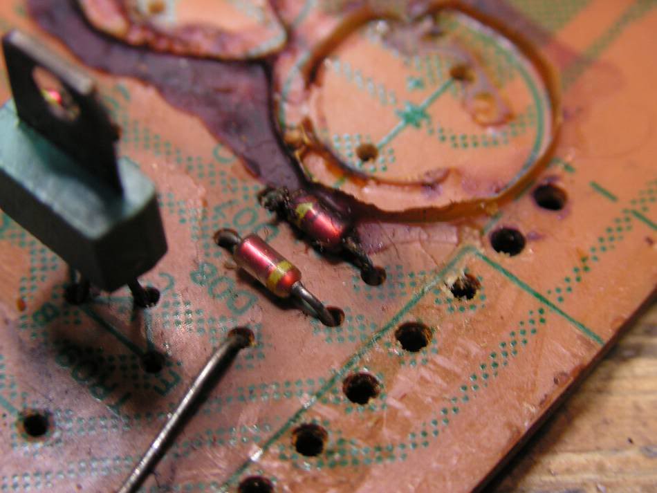
… or look at that small signal diode…
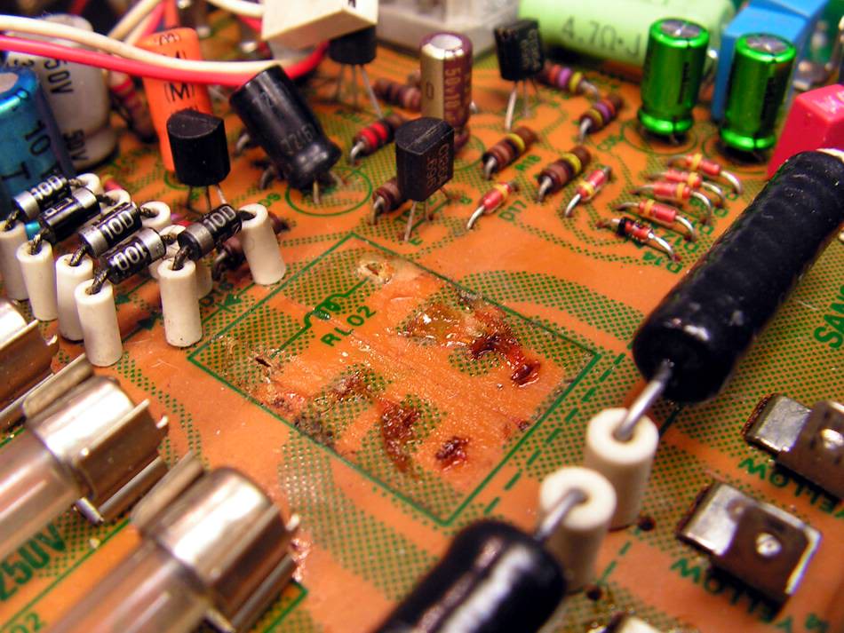
I had a big problem with that:
below old relay was some mixture which was really hard to clean…
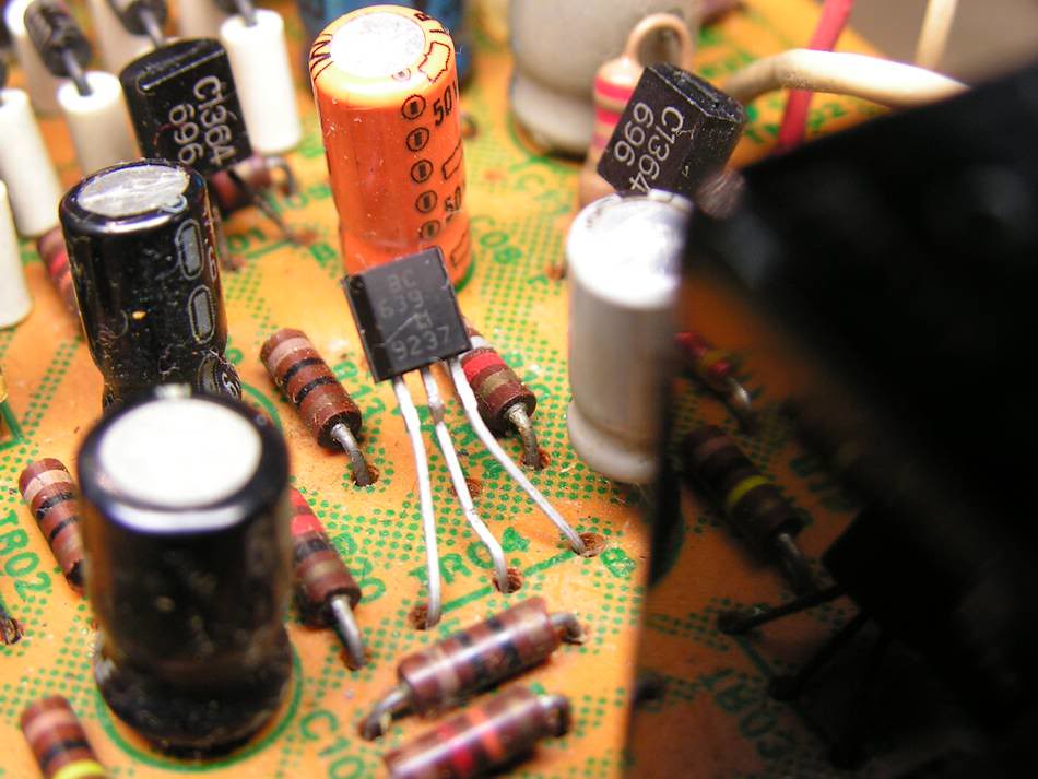
or, that small signal transistor was not original, so I made "undo"
Here they are the main rectifier diodes
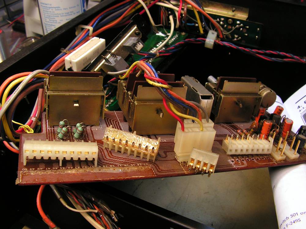
The next job was on, so called, MotherBoard for Drivers board….
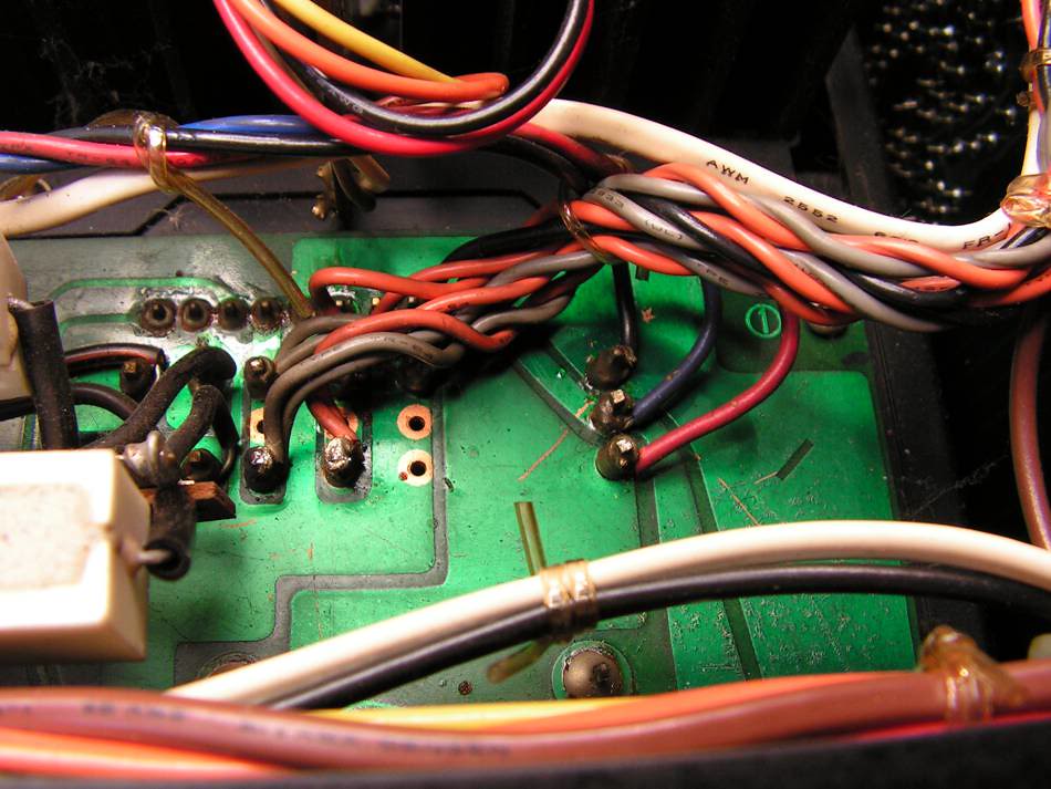
First I have to dismount all those wires
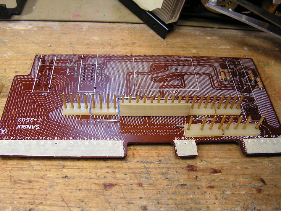
That board was so "greasy" so I have to desolder all connectors and clean them at ultrasonic cleaner
the motherboard is finally out
… after my treatment, it looks now like on that picture:
… and installed back to its location…
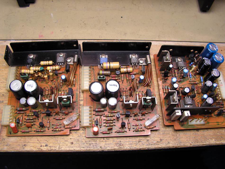
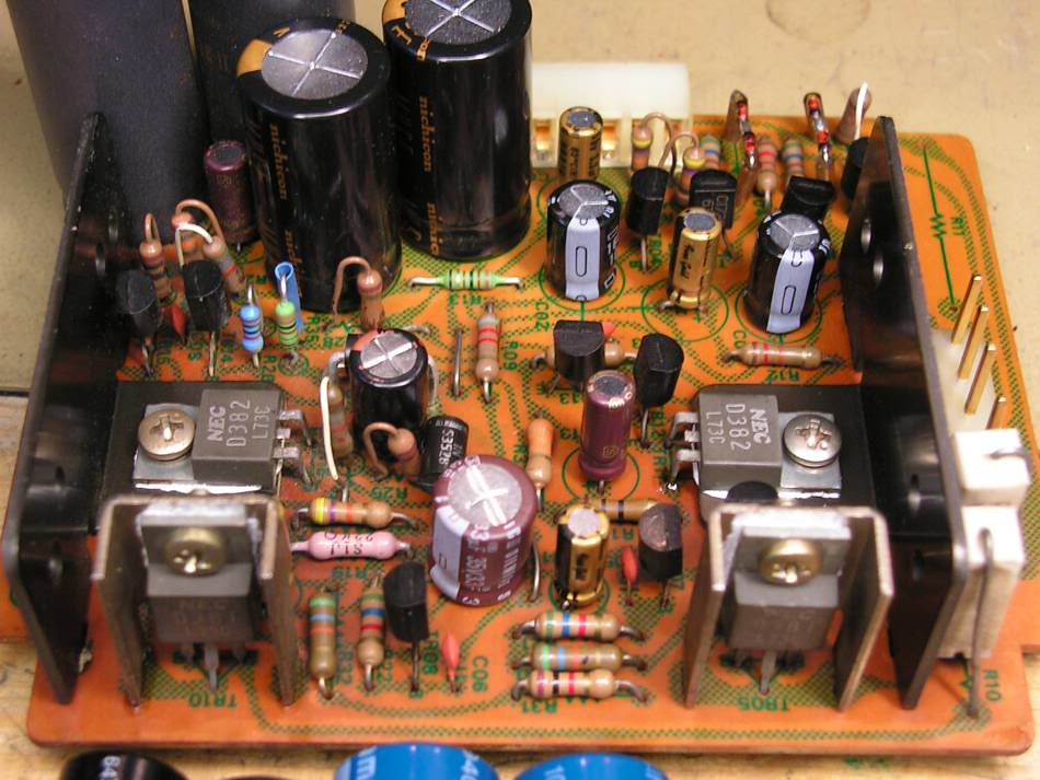
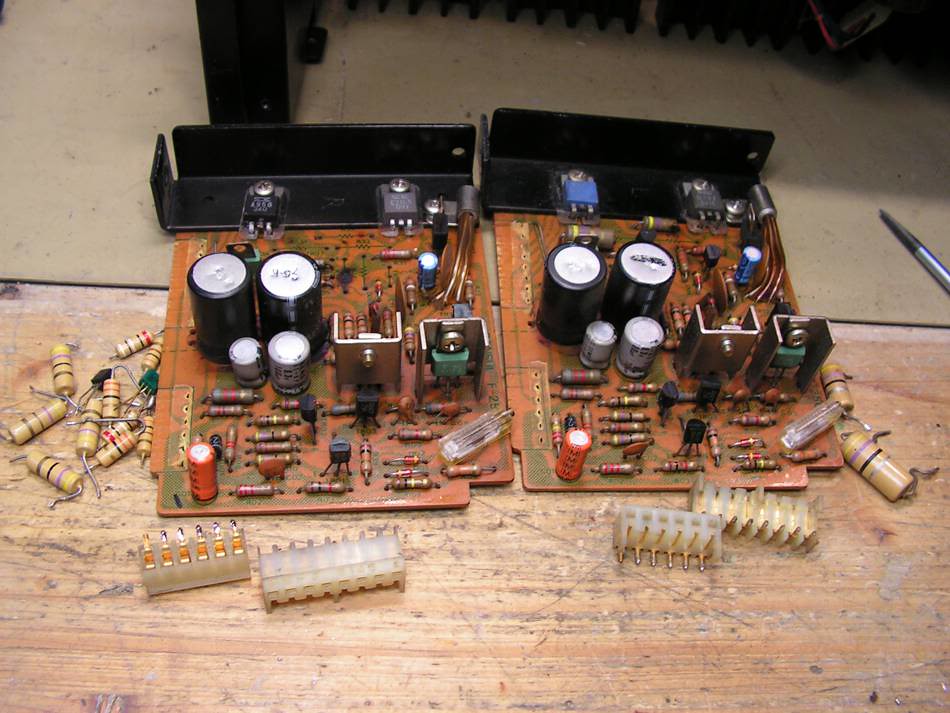
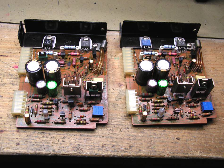
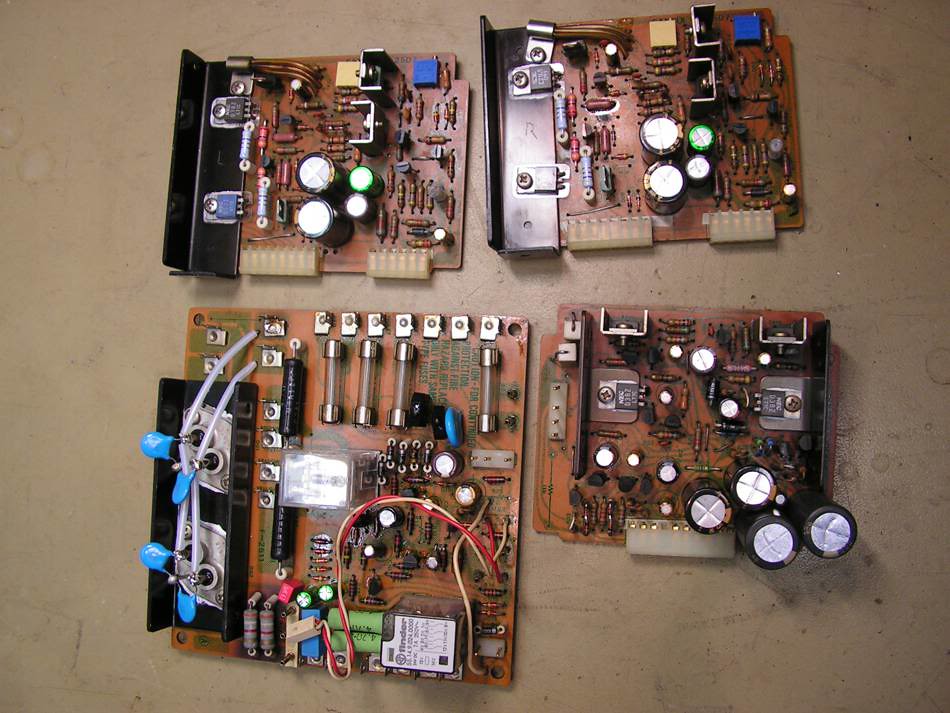
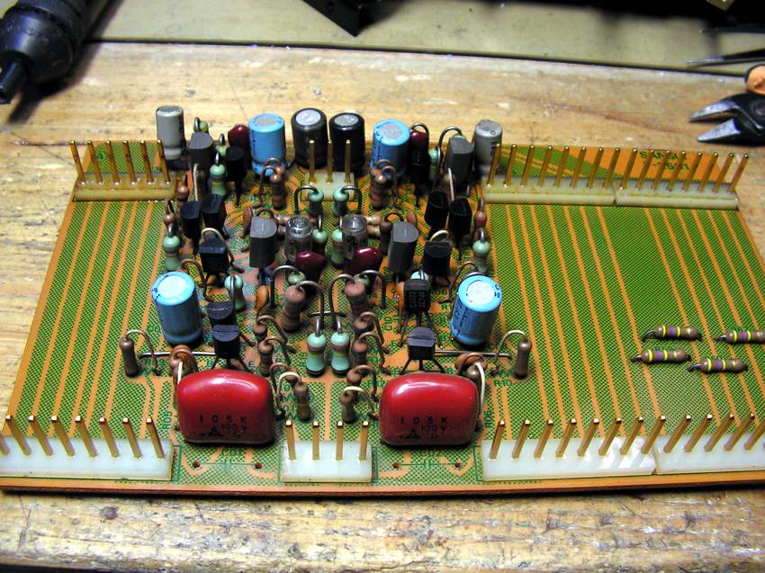
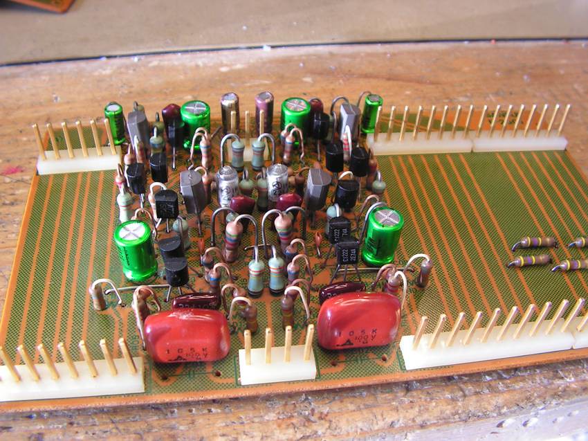
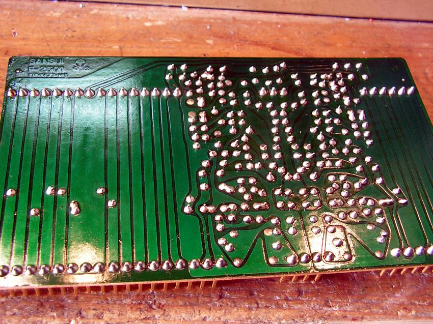
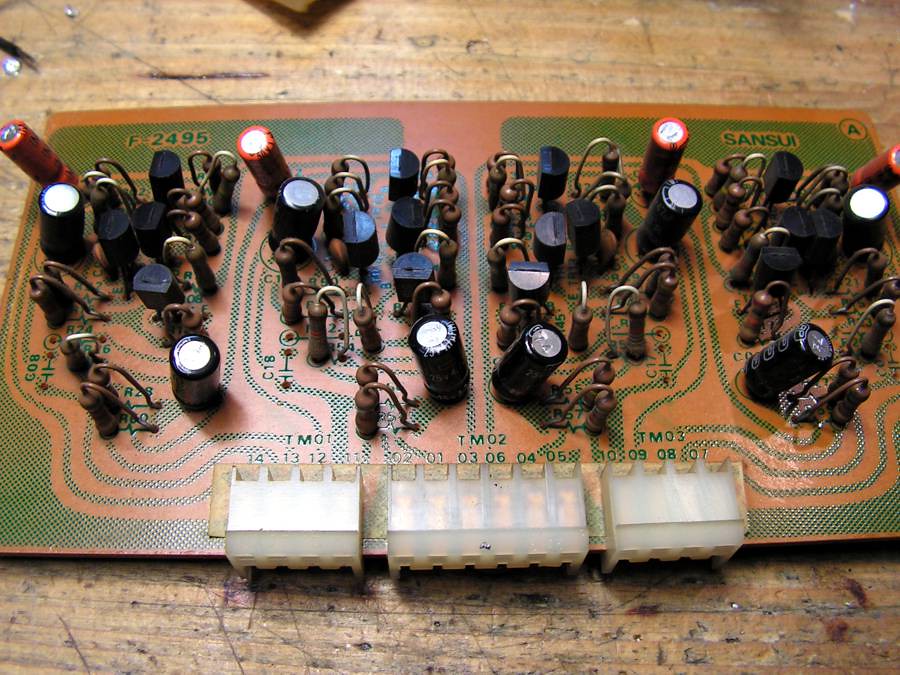
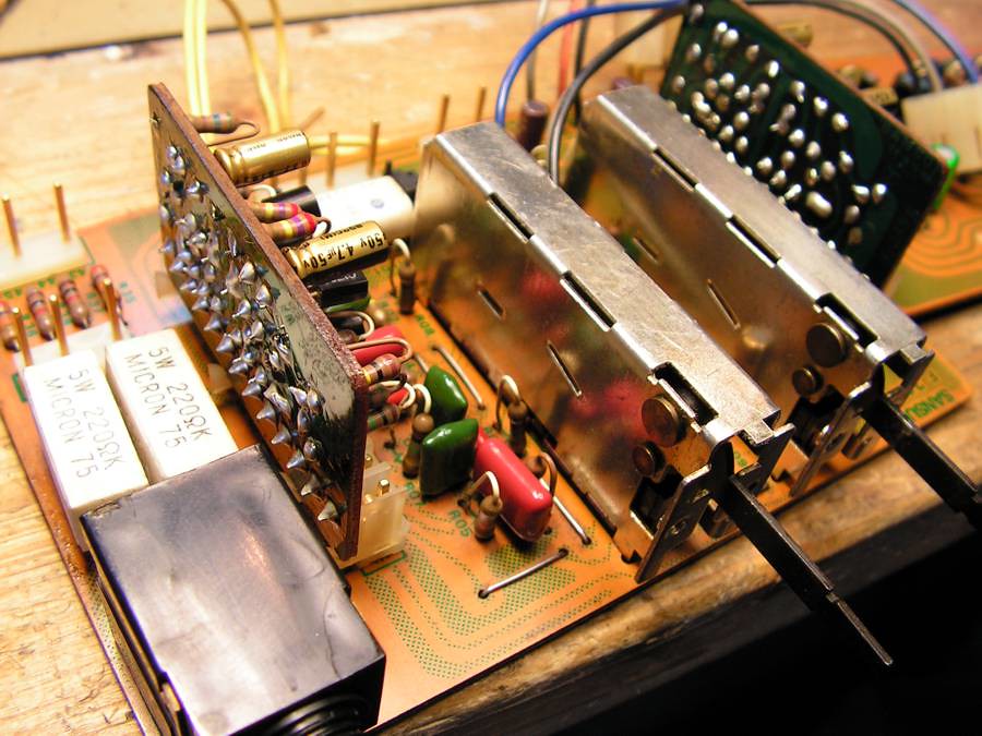
next step was Driver boards and Board with regulated supply
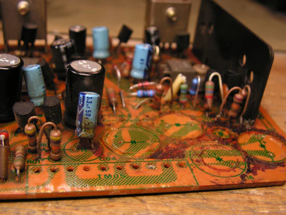
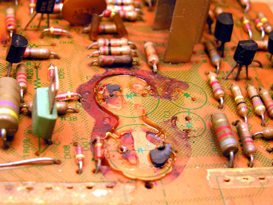
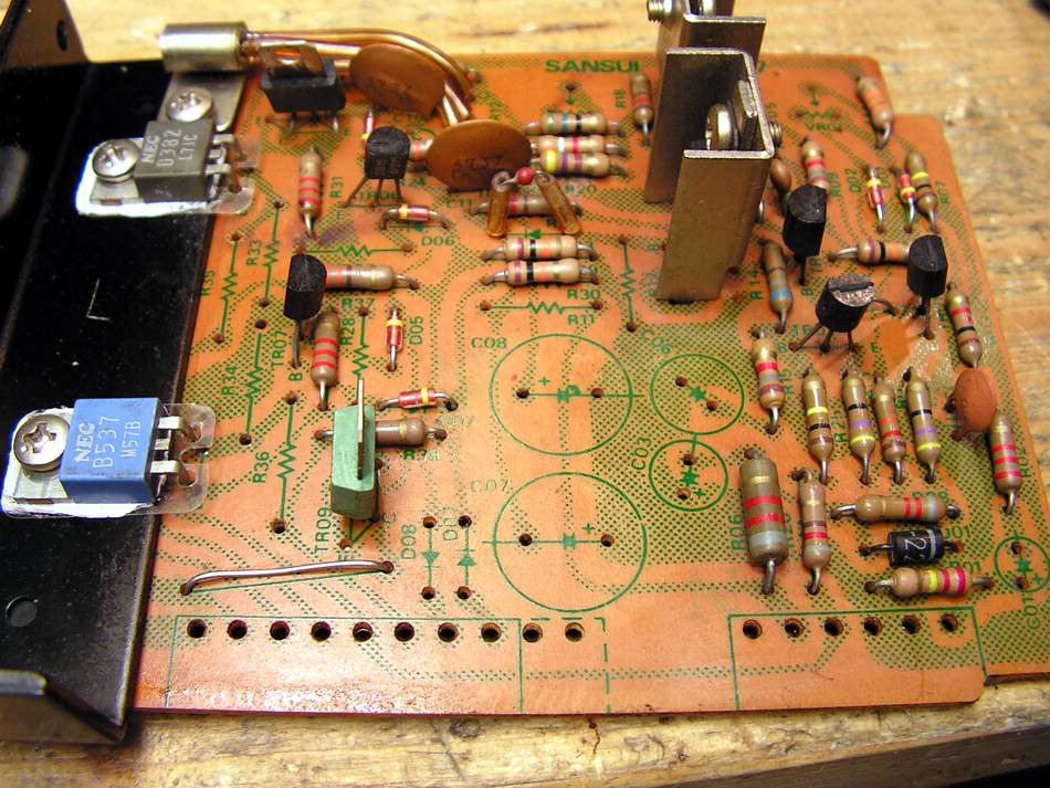
You see, on those boards someone was working something in the past too…
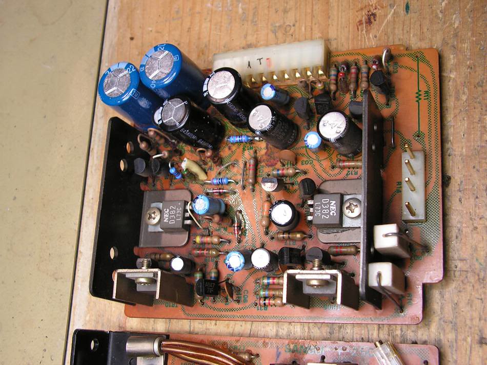
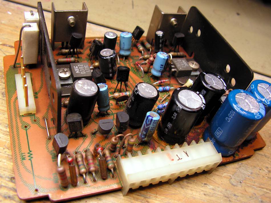
So let's start with regulated power supply board
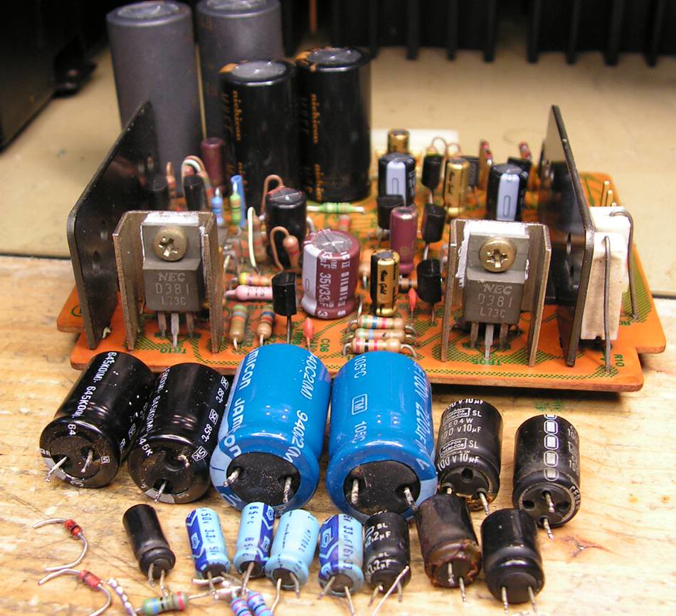
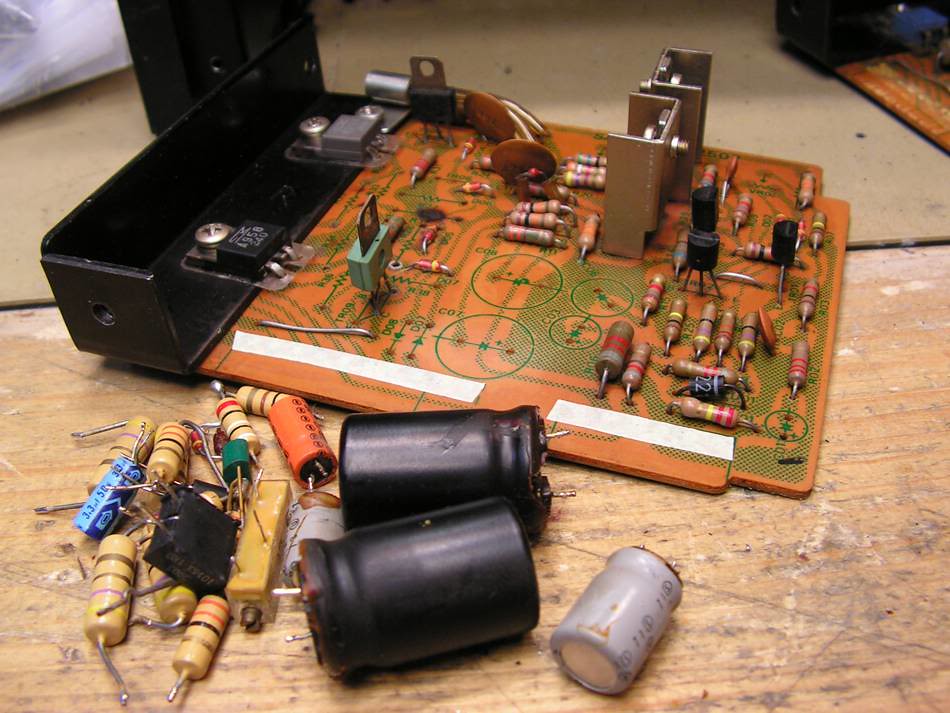
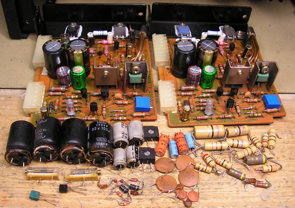
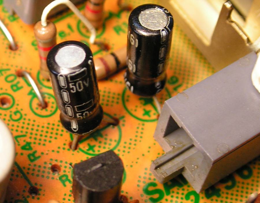
these capacitors were changed in the past, I dont know the reason, but I decided to change them all with my favorites capacitors (Elna and Nichicon)
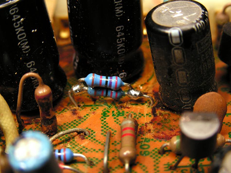
… look at that service job
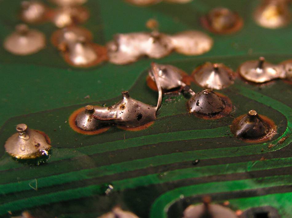
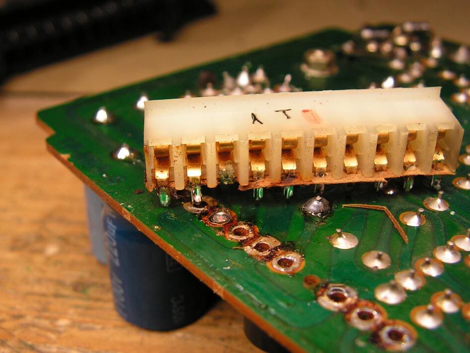
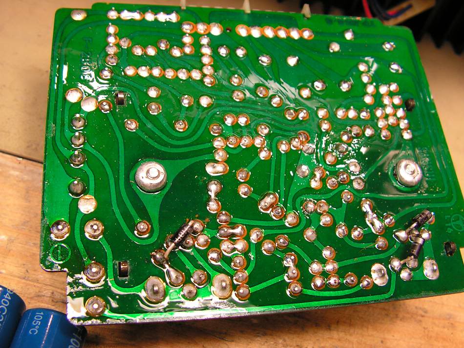
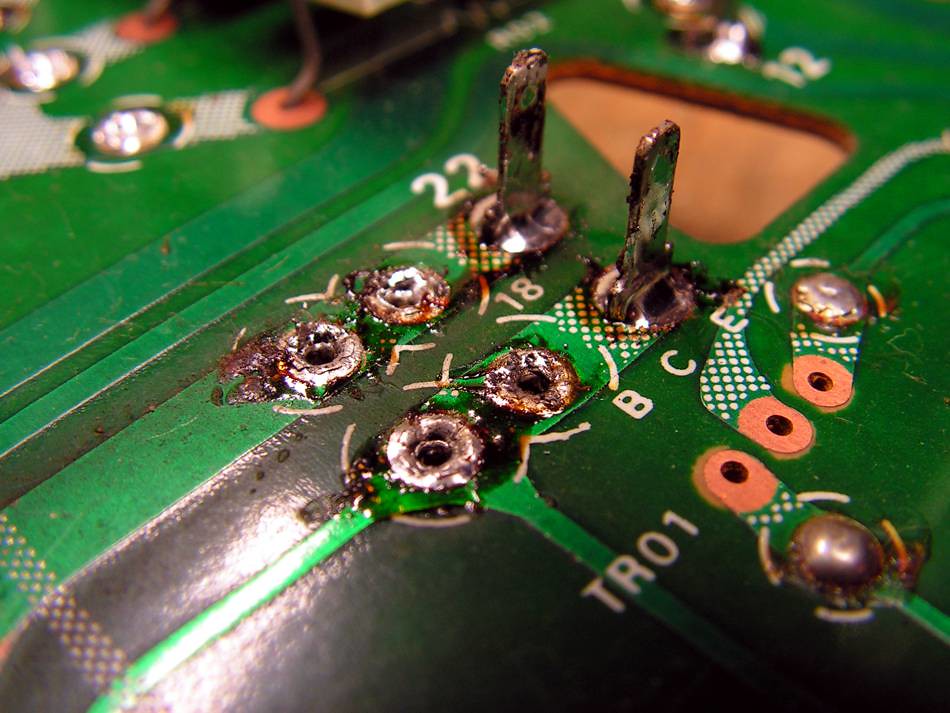
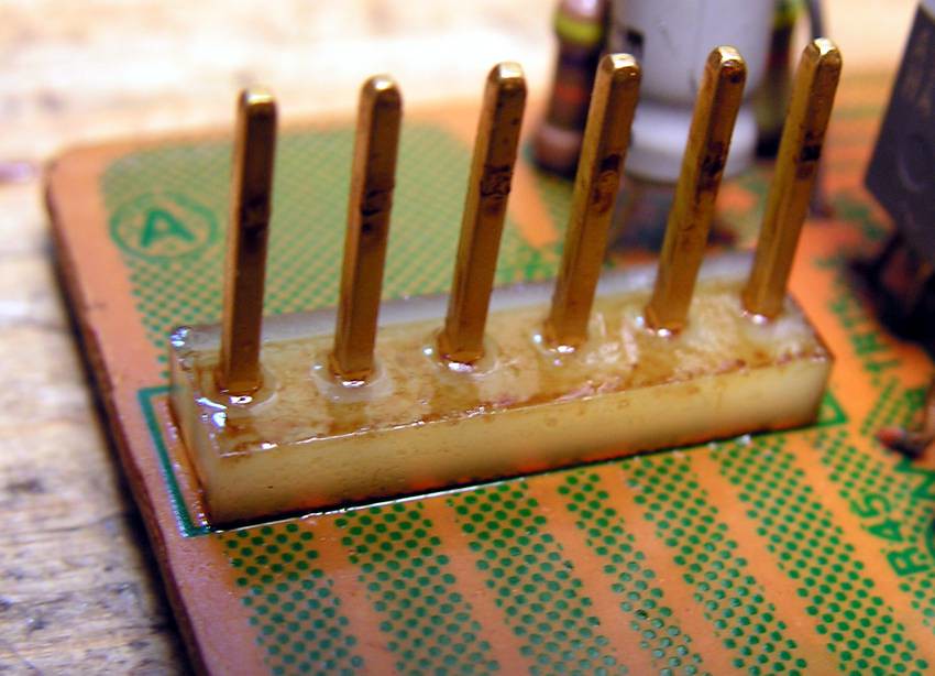
But the most interesting thing was this connector
.. what… you still don’t see…
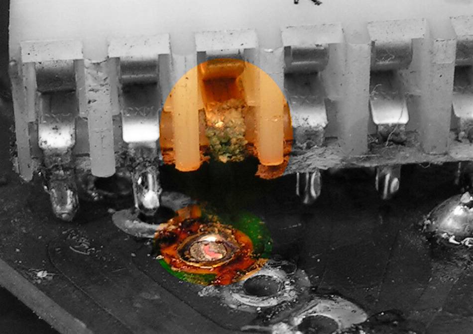
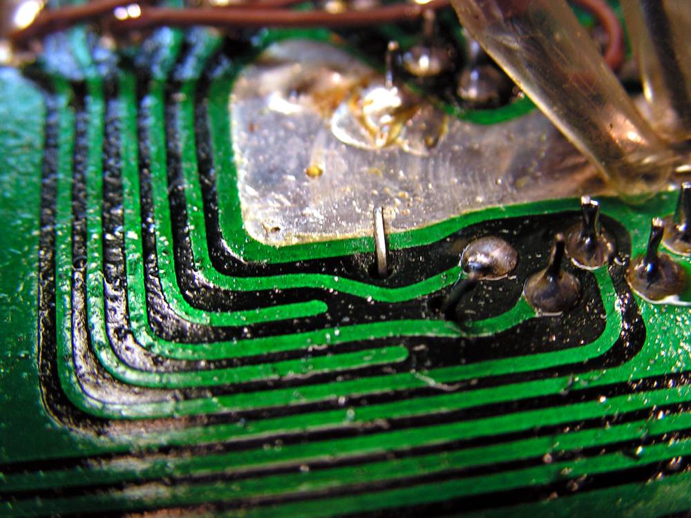
Ok please take a look at this picture below:
That pin was broken because of corrosion !
The next job was cleaning that glue
And at the end, this is the result
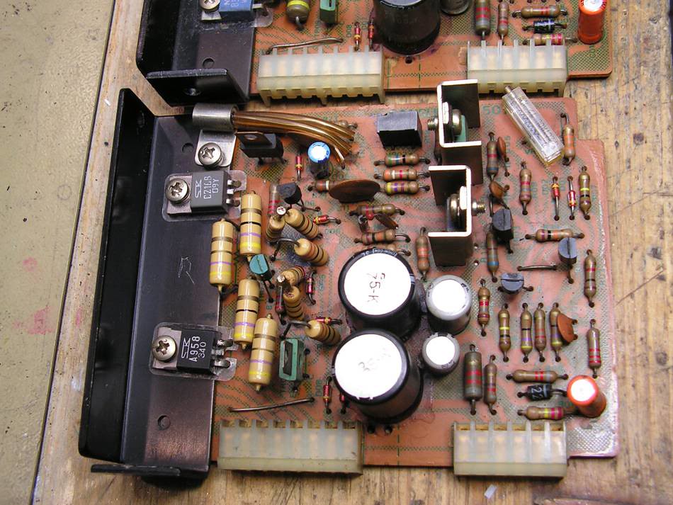
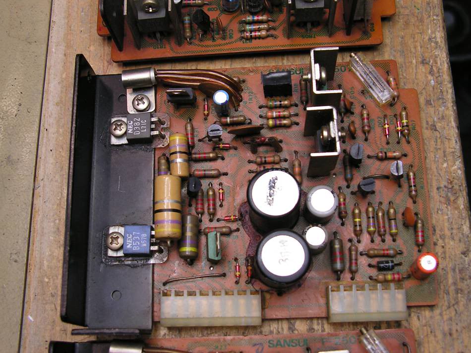
OK, let's continue with driver boards…
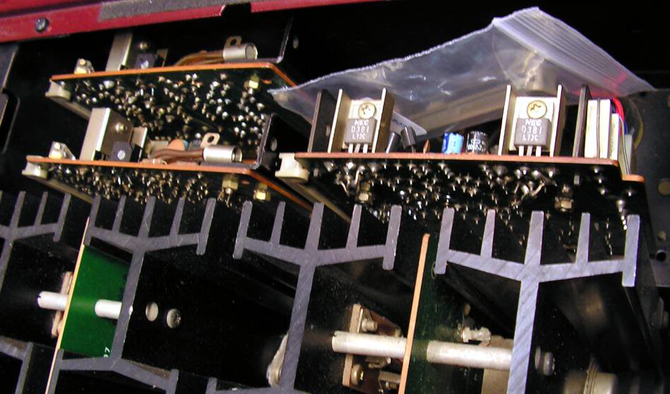
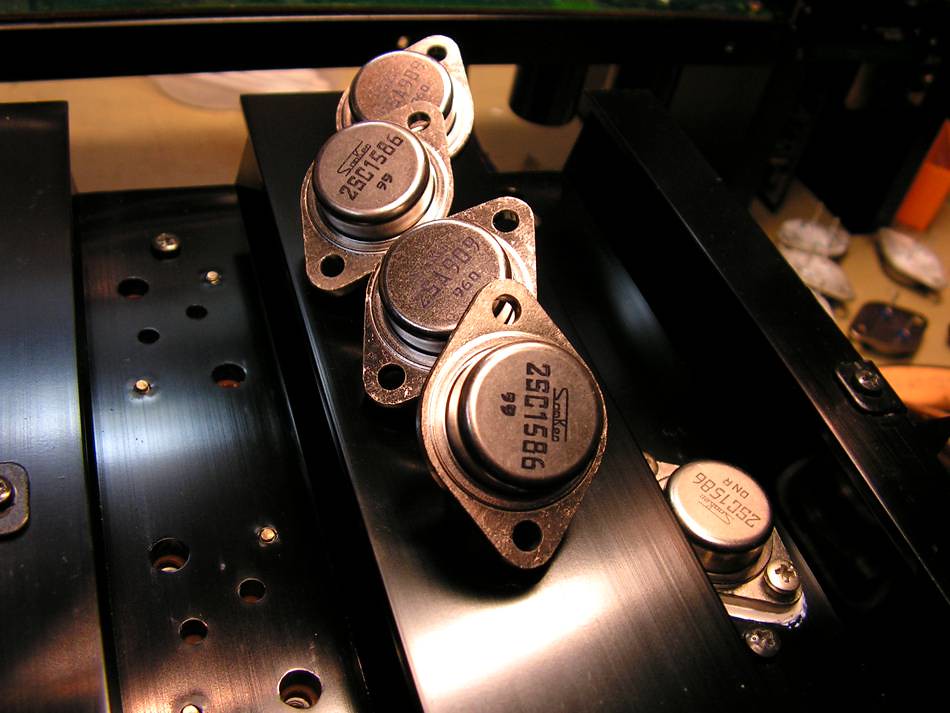
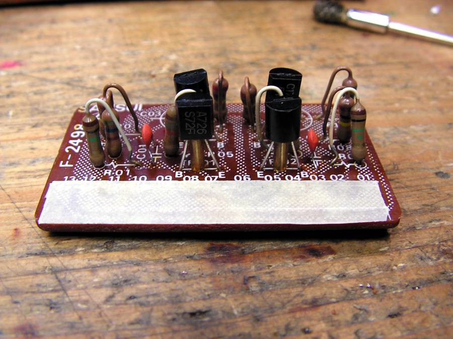
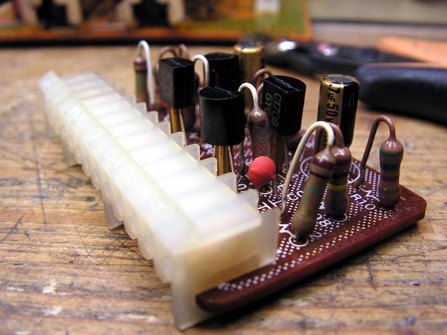
As you can see they have one interesting detail; drivers transistors are different on those two driver board, but they are genuine, and Sansui used the both pairs in theirs amplifiers as driver transistors. But it is interesting what they are not the same pair on the both channels.
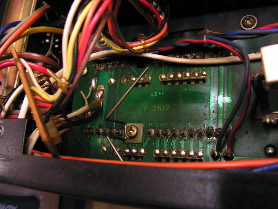
… preparing for cleaning connector
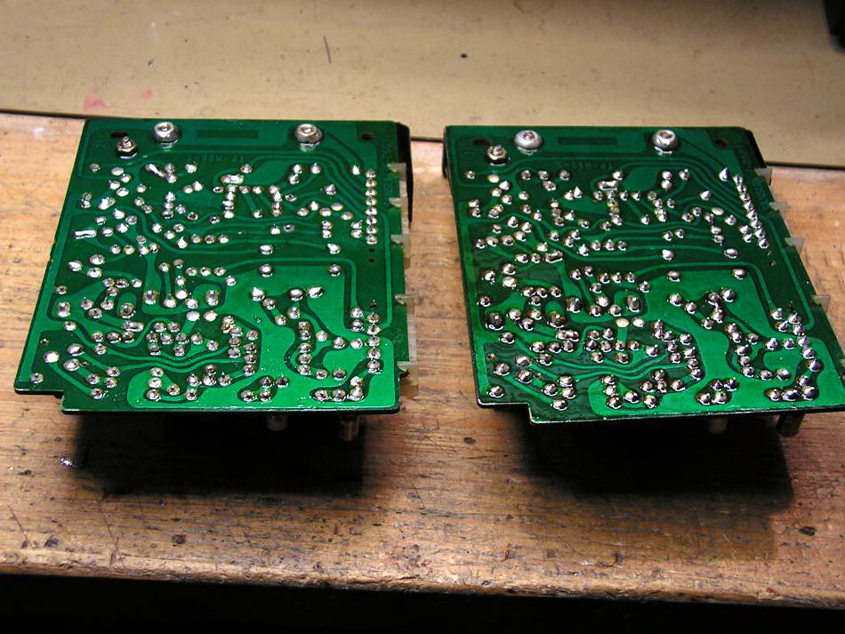
… again glue
… what I am going to replace
… in the middle of desoldering job
… glue again
… is it clean now
… what I replaced at those two boards
… and one view below
… and one above
so what I have done until now
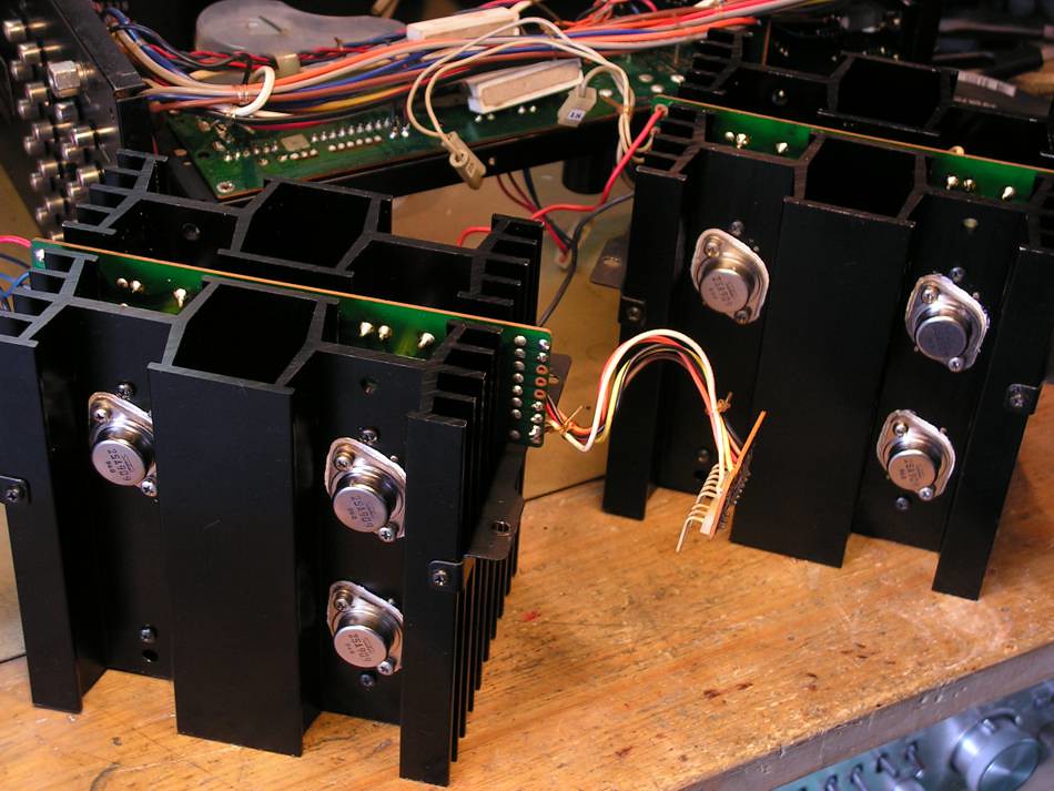
The next step was power stage…
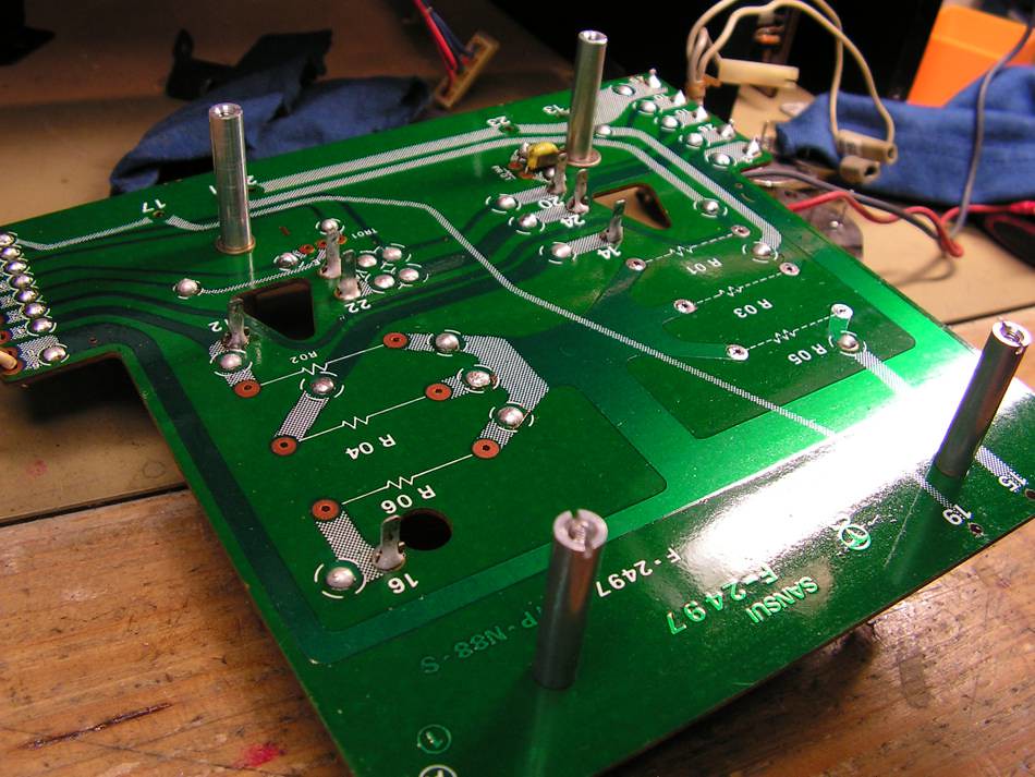
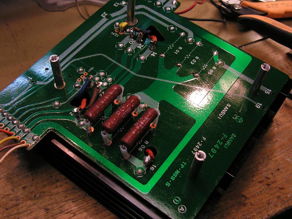
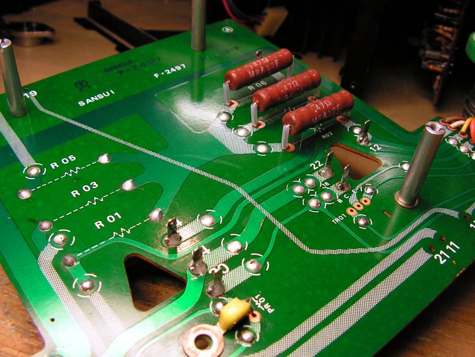
The picture below is final result, but to get that result, you should work really hard…
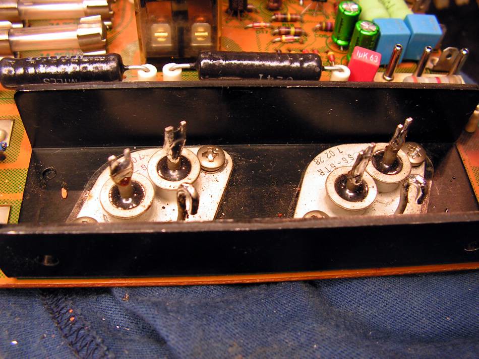
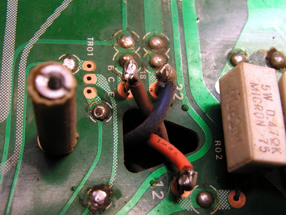
To dismount the power stage you should remove some wires which goes from TO3 sockets to board…
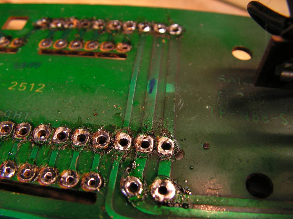
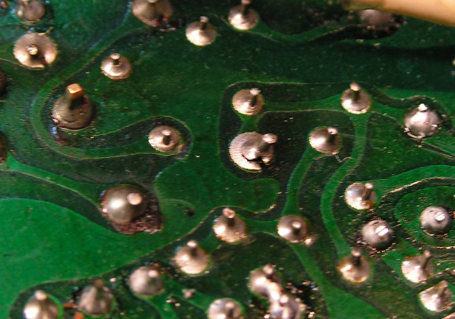
beside those two pins, you can see the holes which are used for transfer of electrical connections from one side of board to another side. You know, that is double side printed circuit board.
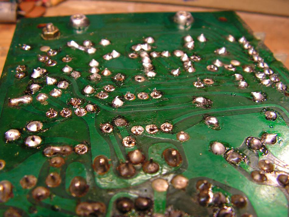
Because of age, those connections could be bad, and because of that you should remove old solder, and put the now one…
Here you can see how it was
Those two screws are not original…
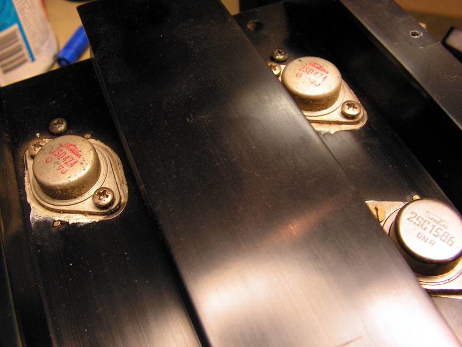
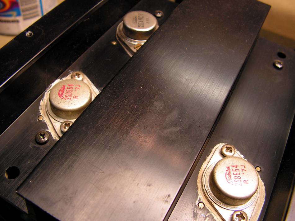
Hm, strange… genuine Toshibas beside genuine Sanken
the same on other side…
Now, take a look how it looks like now (the board I mean)
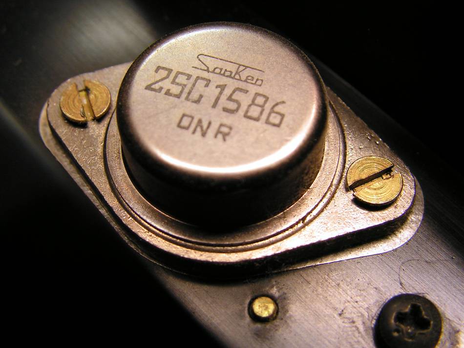
and finally NOS genuine Sankens
TO3 sockets were cleaned by ultrasonic cleaner
Don’t worry… this is not some broken AU20000, just this is one in the cleaning phase during my work on that amplifier
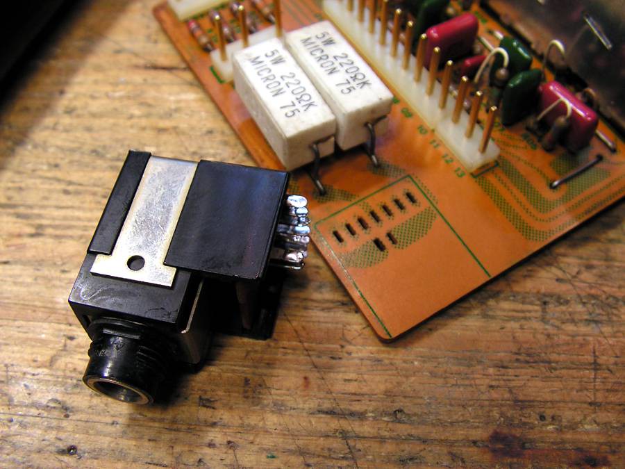
… cleaning RCA connectors
… cleaning switch at the same board
Look what I have found
that Zobel filter was burned out, and what is interesting, the burned resistor was not original
OK, it is fixed
And now you will see the most interesting part at that restoration job…
First, I have to remove the front part of chassis
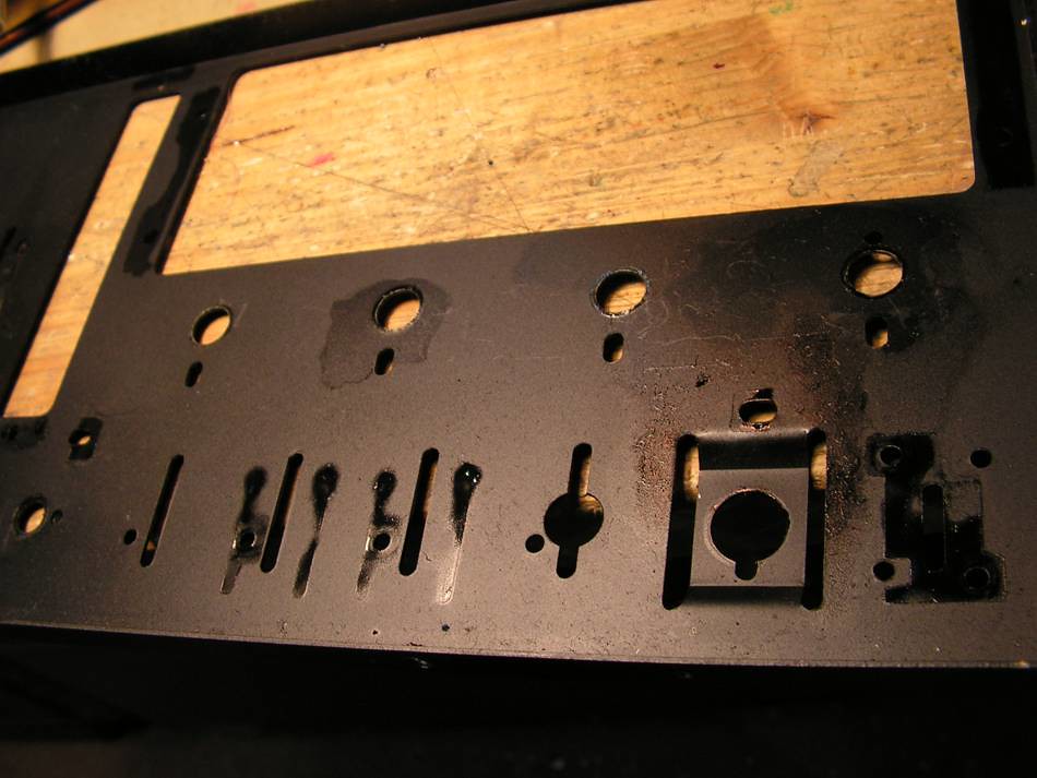
and this detail show to me there will be problem with that oil or grease
And please take a look what i have found
or this
can you believe that is electronic board
BUUUT, it looks now like on this picture
What you think, can that switch work normally at that condition
but now it would
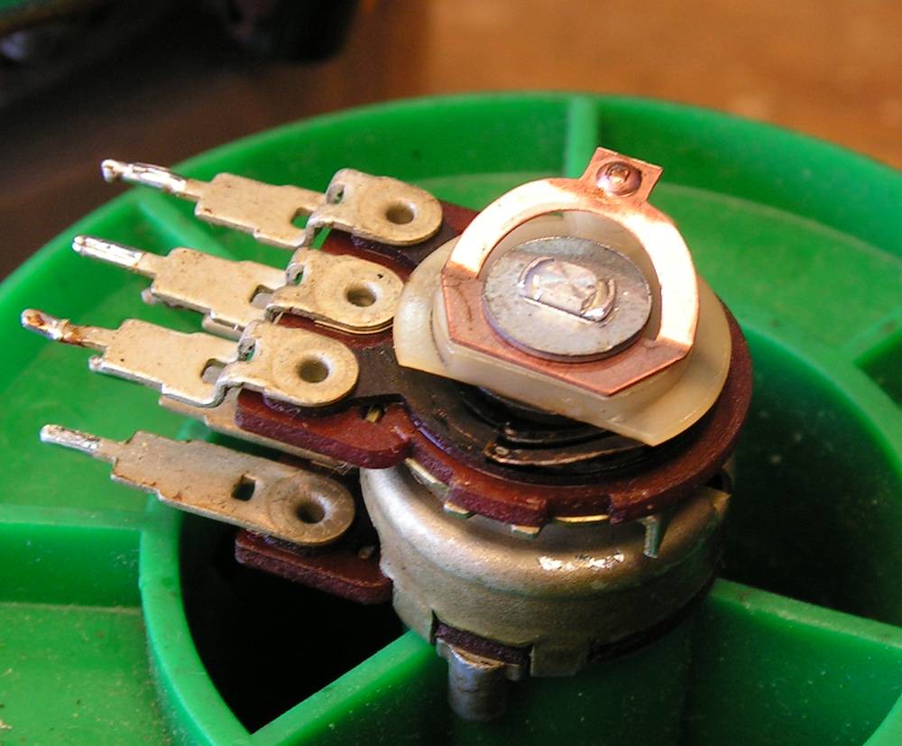
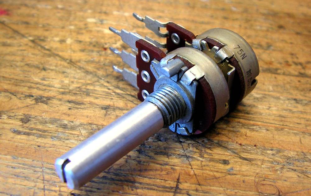
On the next picture is volume pot, how it was
and how it is now
And finally
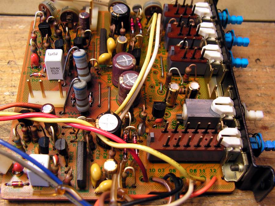
The next step was Flat amp board,
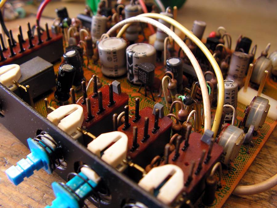
but there I have found traces of grease too (below connectors)
after cleaning connector…
and finally after recaping…
… phono preamp
again grease problem…
… finally
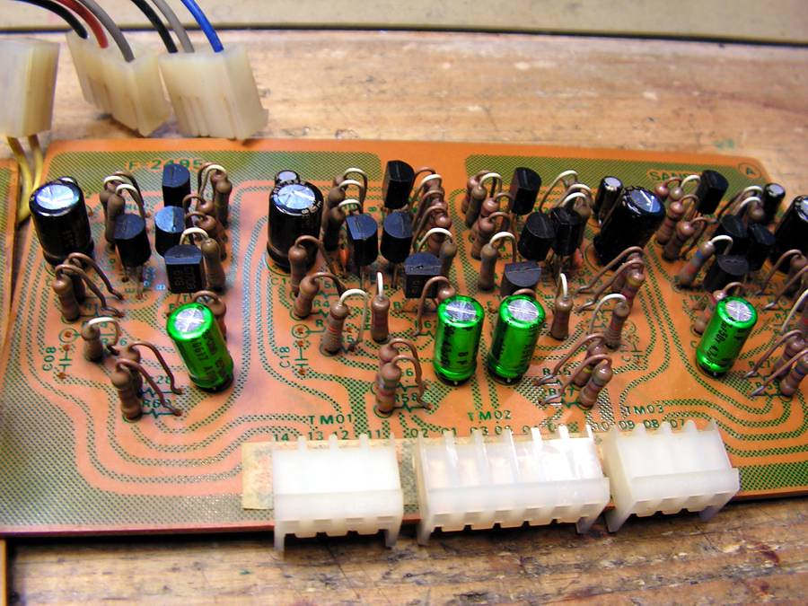
… Tone Amplifier Board
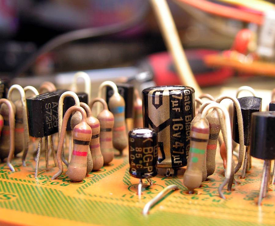
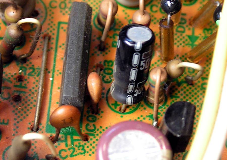
I forgot to mention; all small signal transistors I pulled out to check Hfe, and if it is as it should be, it was soldered back to its place.
… a little spice
… and finally
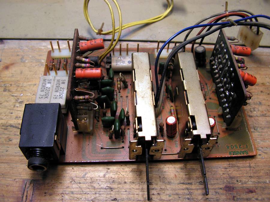
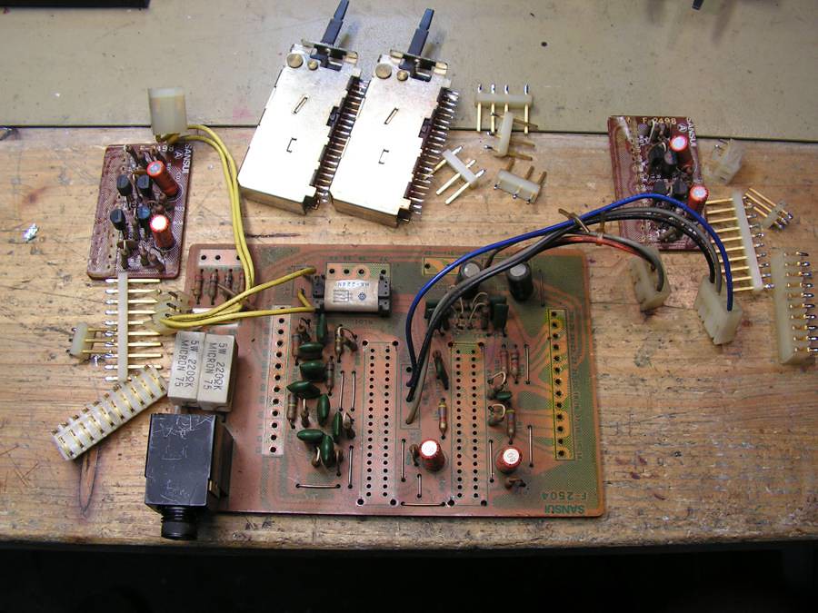
… Filter Board…
… ready for cleaning…
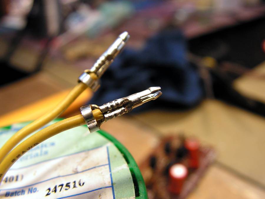
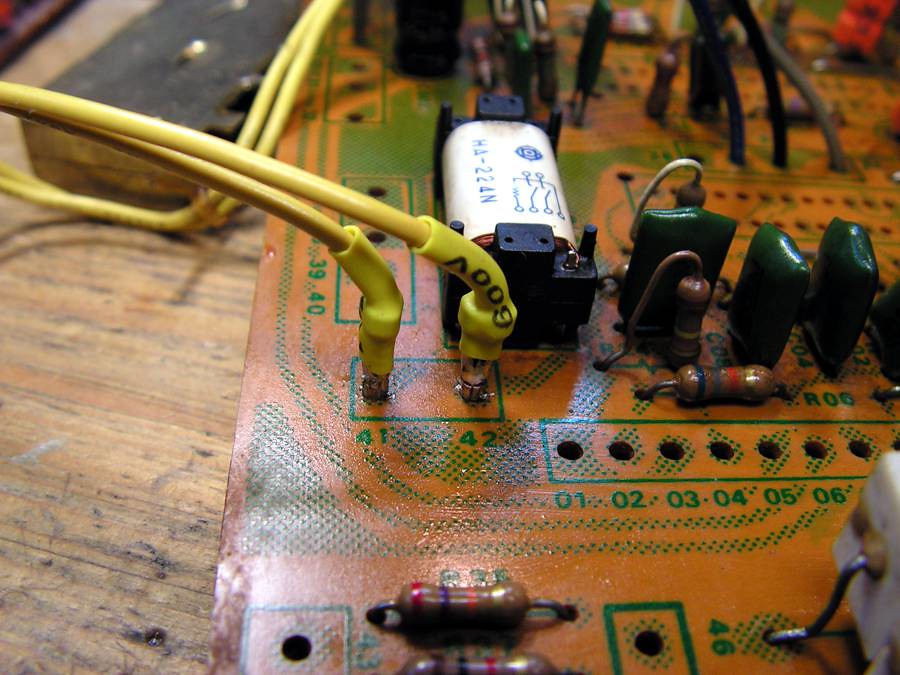
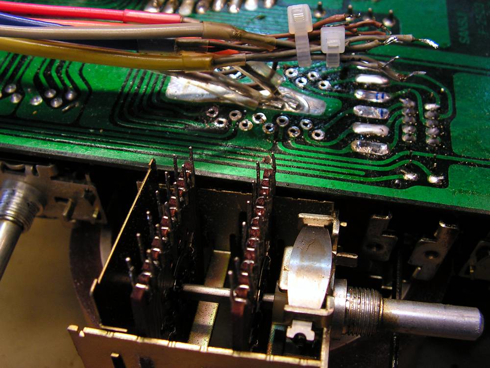
but here I have found that yellow cable was broken because it was soldered directly to board, so I decided to connect it on that way
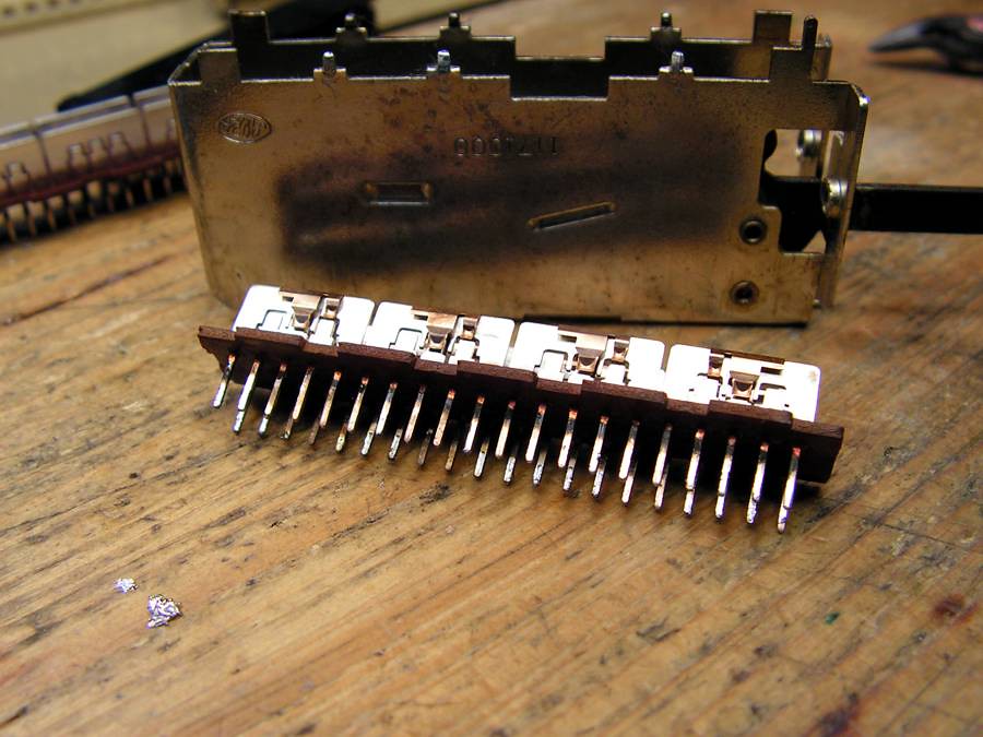
… cleaning the switch
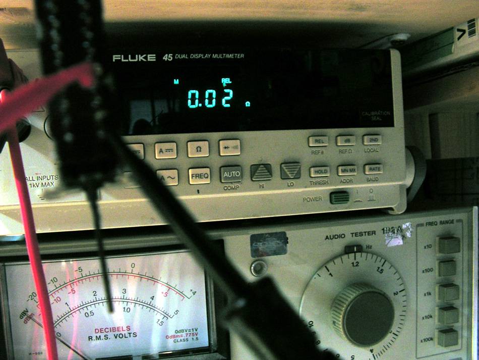
and checking contacts crossover resistance
that FLUKE has feature to measure very small resistance without test cable influence.
… more cleaning…
… and finally
Meter Circuit Board,
… again grease problem…
… cleaning switches
… and one interesting detail, look at the marks on the board and then look marks of polarity of capacitors
… again the same thing
one problem with solder point
… and finally….
The Tone Control Board
Potentiometers ready for cleaning
is it like new now
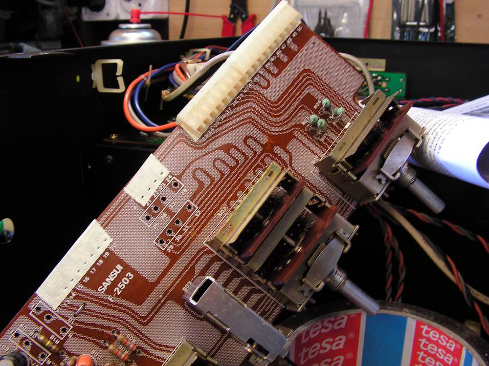
Output Selector
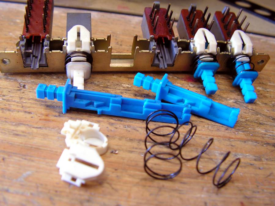
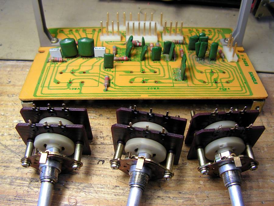
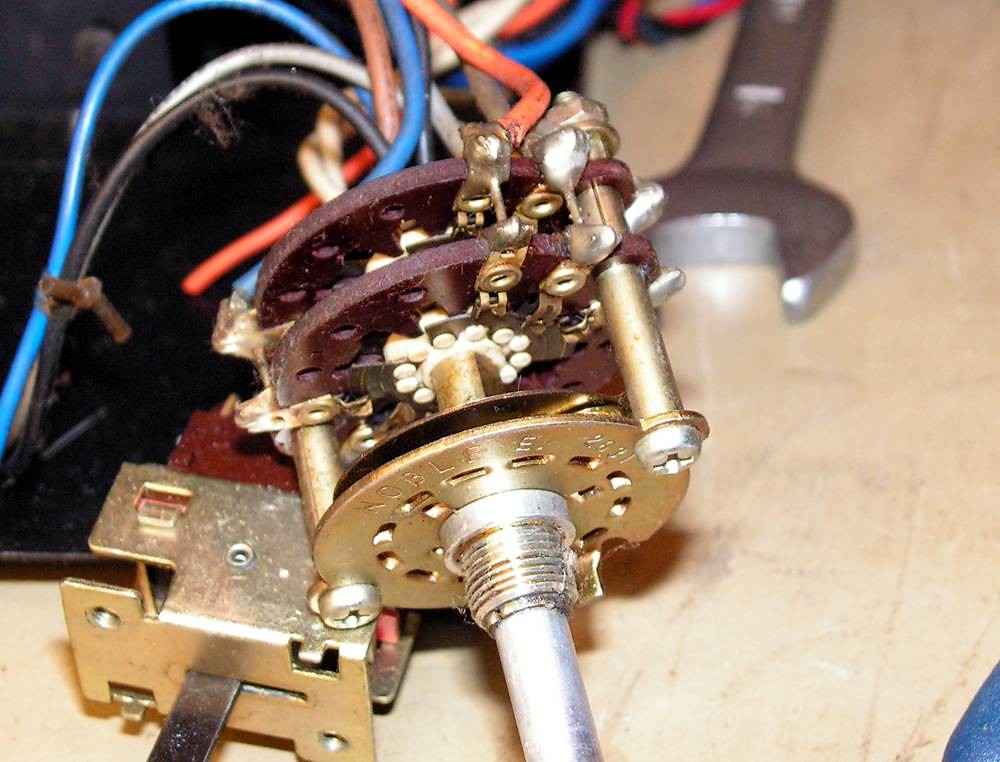
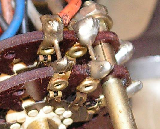
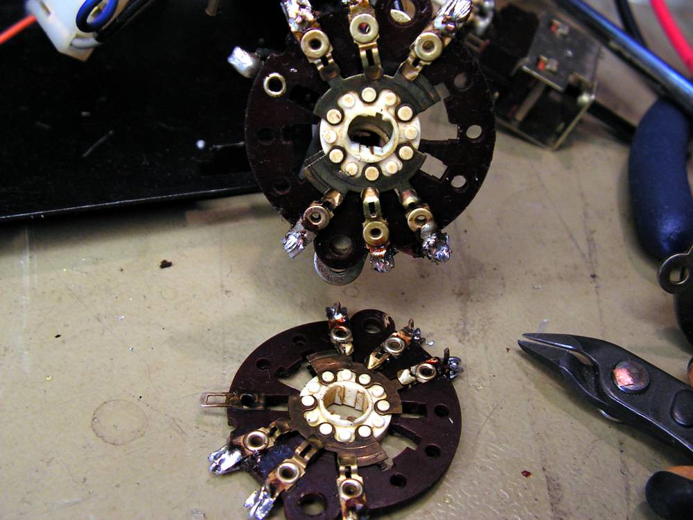
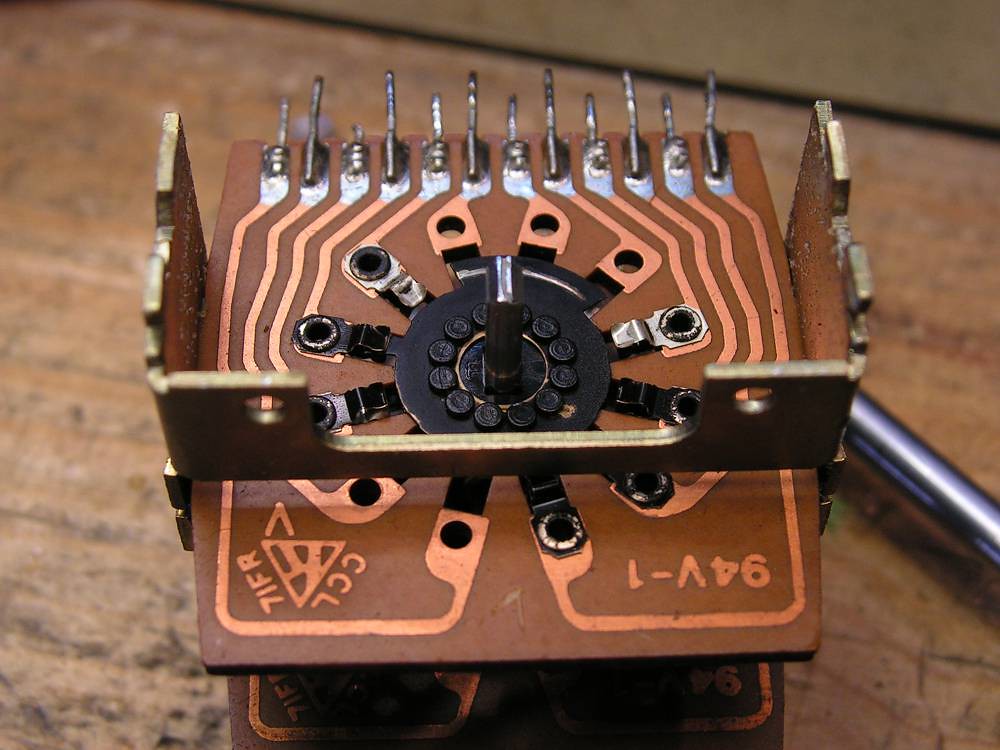
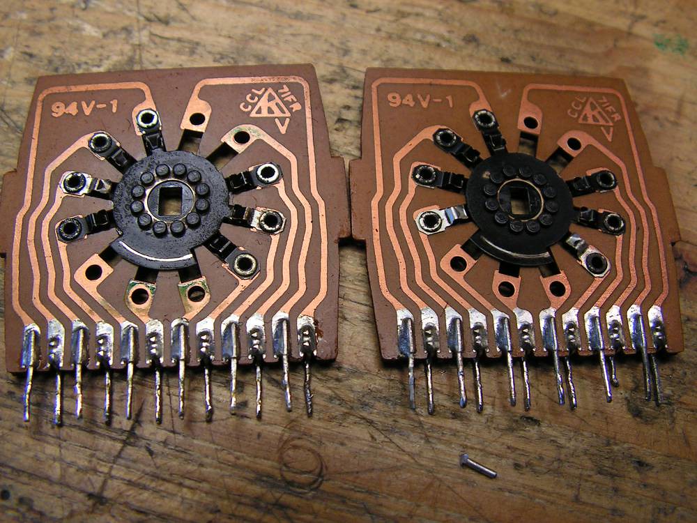
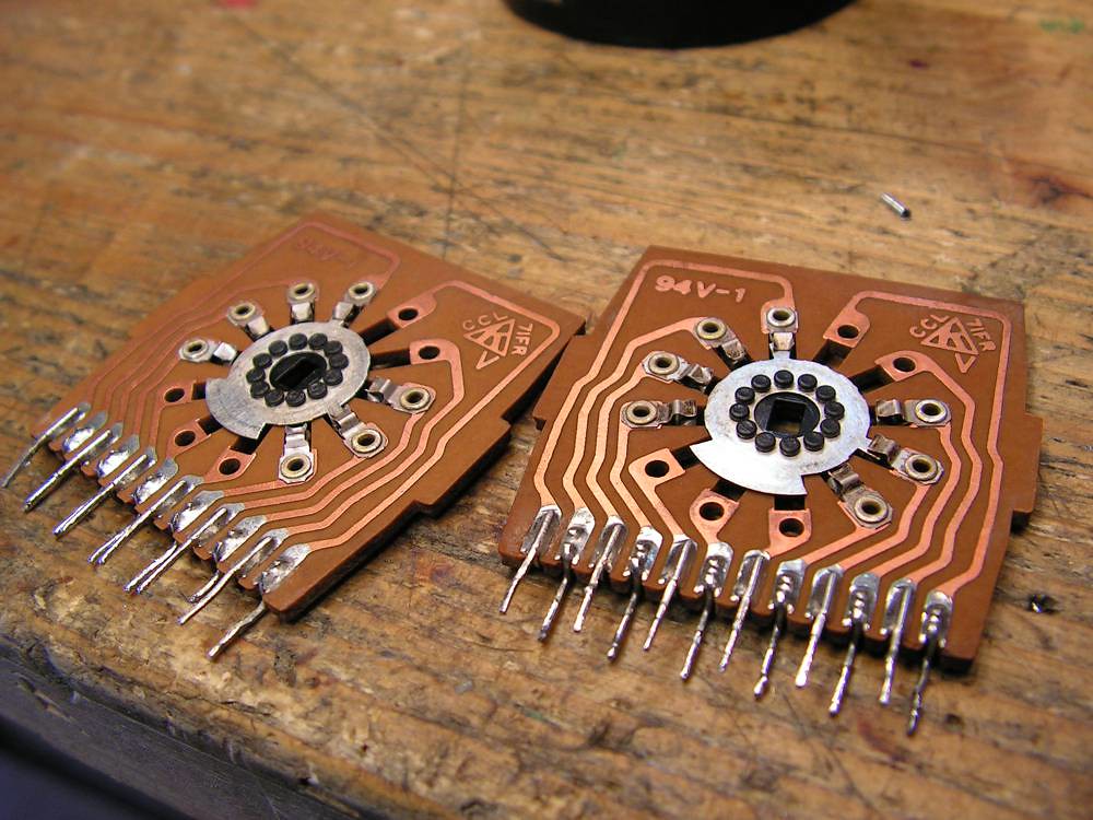
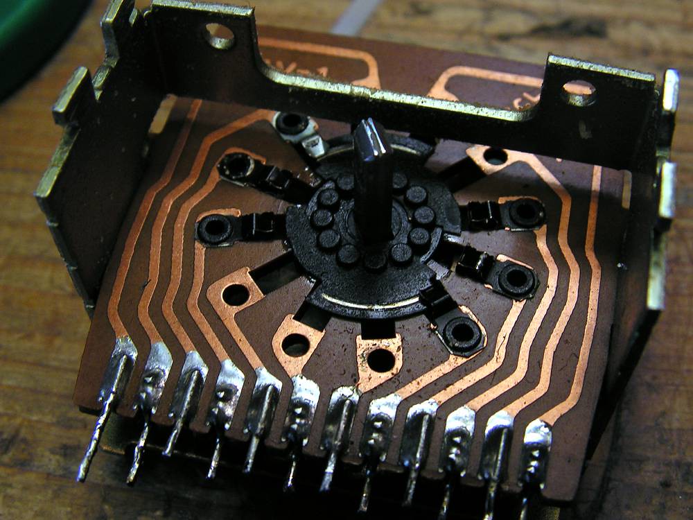
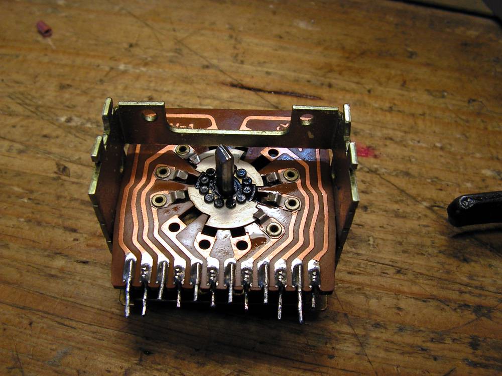
Sansui used two the same wafers for each contact to reduce crossover resistance but it is really hard job to dismount the both wafers to clean them
you see now about what I was talking above:
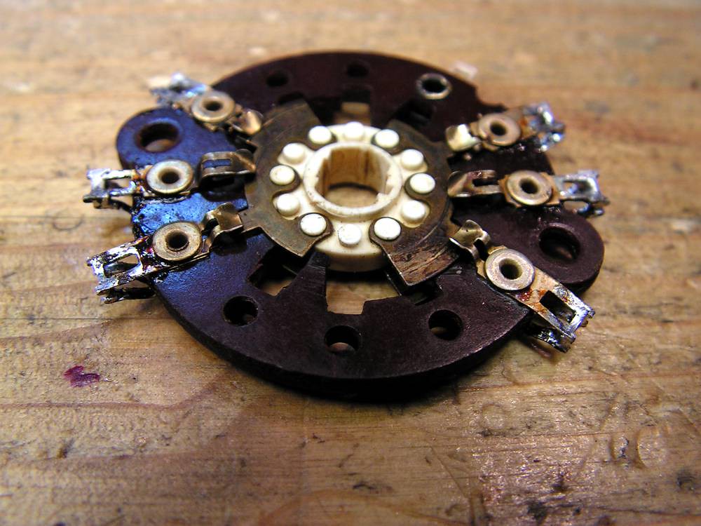
ready for cleaning
again like a new
and connected back to its place
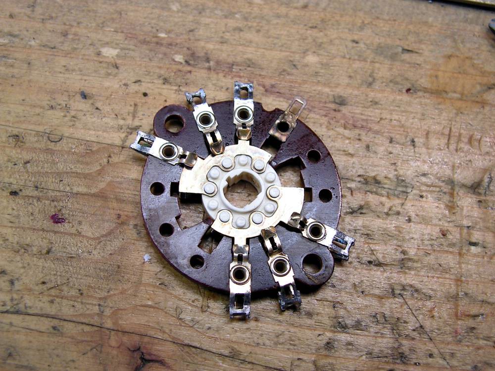
And now, Tape Copy Selector… but first you should see this
this is one unused pin of that selector, but it is bended on wrong way
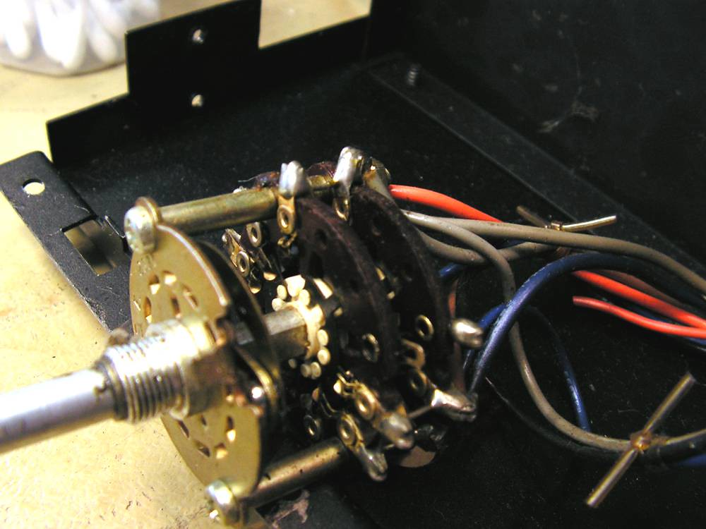
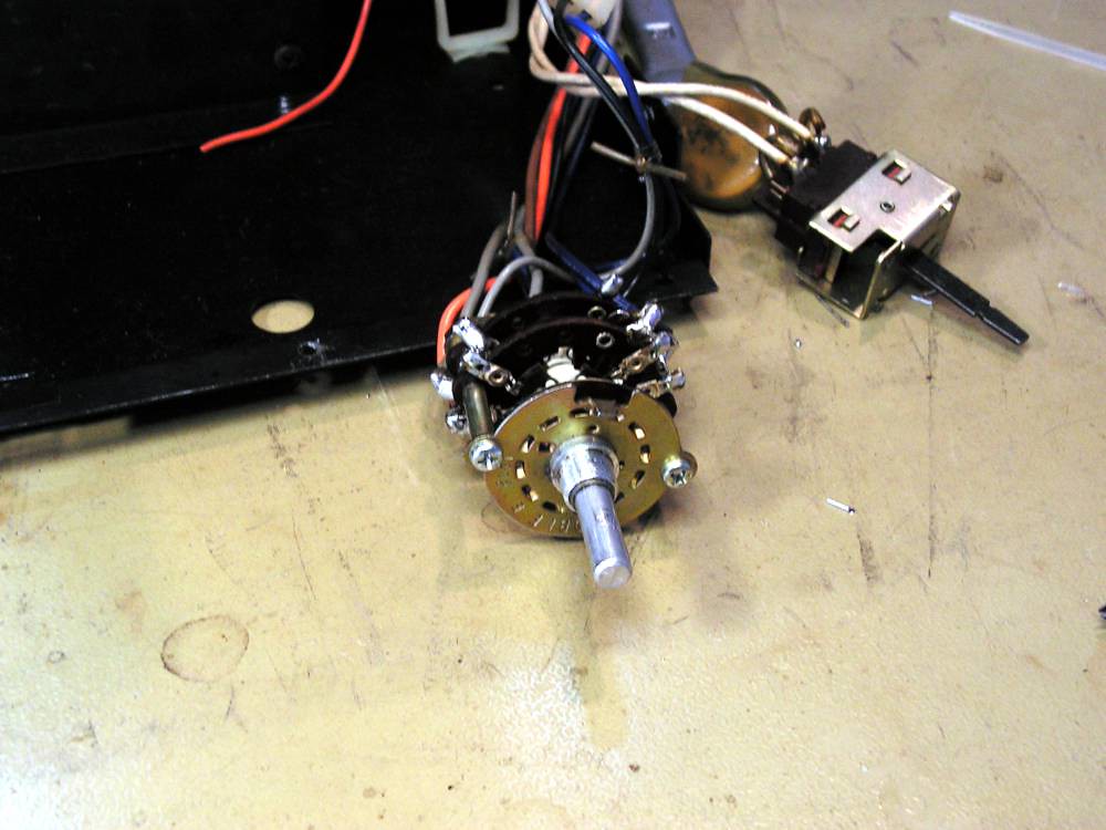
To dismount that selector, you should remove all small signal cables
very demanding job…
finally it is out
here you can see how it was looking
the both wafers ready for cleaning
and like new…
The same situation was with Sensitivity selector
and with Mode Selector
… cleaned…
again cleaning…. cleaning… and again cleaning…..
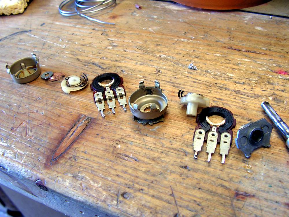
here I have found a problem with Balance pot… it had a bad contact, but it is not simple to dismount it, look at the next picture :
the shaft of potentiometer is nailed, and you should remove just only small part of that, just enough to separate the shaft from other part of potentiometer.
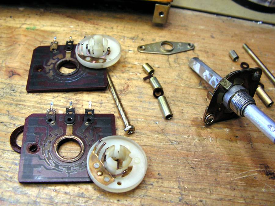
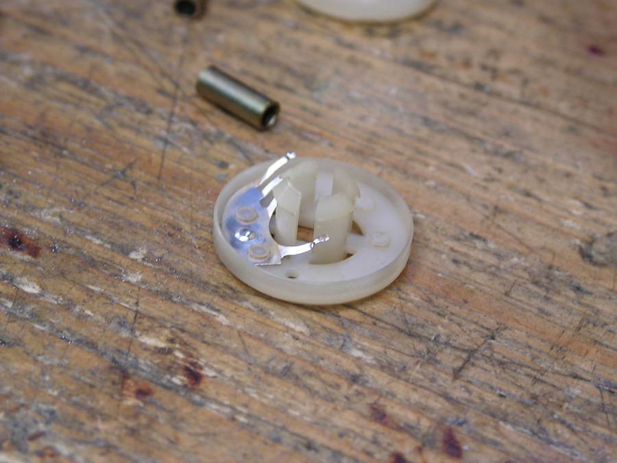
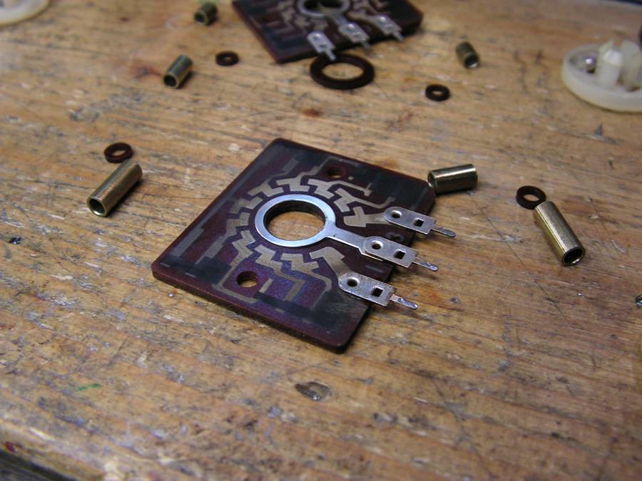
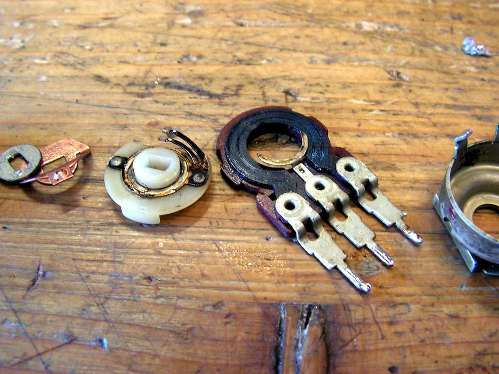
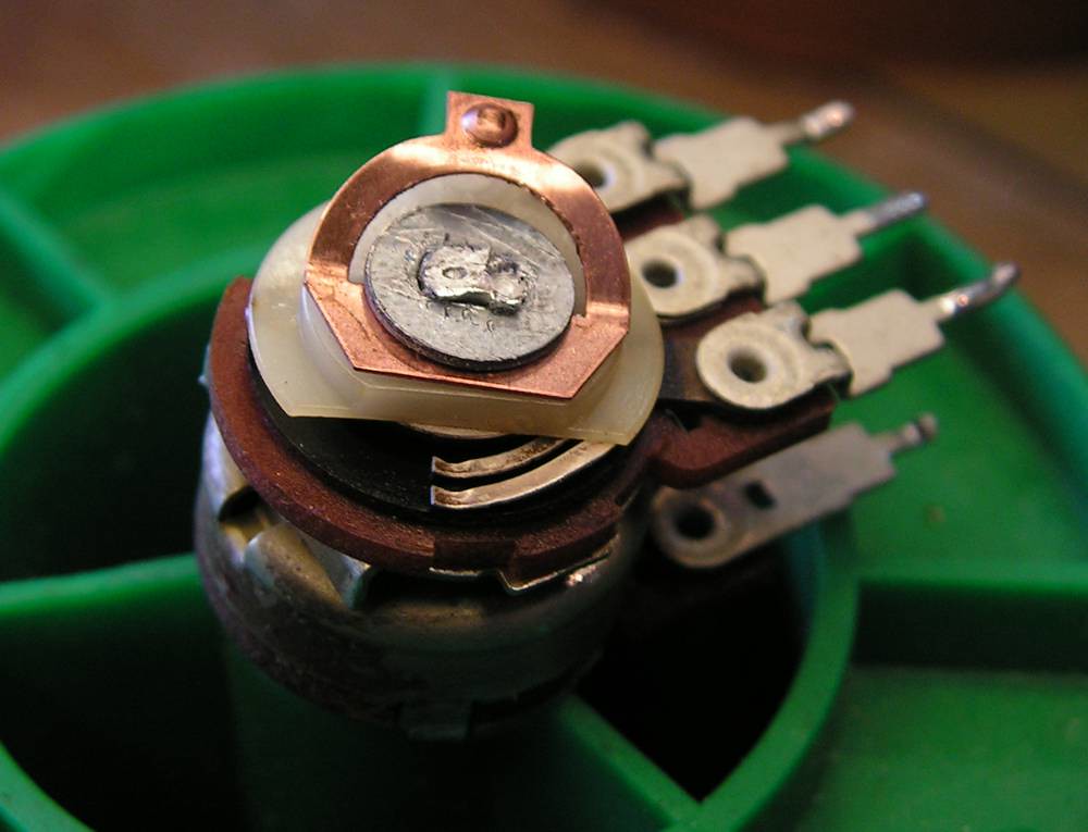
Here you can see all parts of Balance potentiometer
Now it is clear why it had bad contact
and again assembled
and here it is, like a new
Ok… the small signal cables soldered back to theirs place
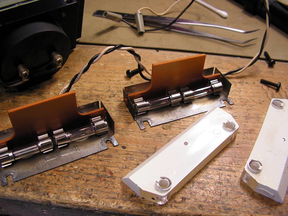
and now light of power meters…
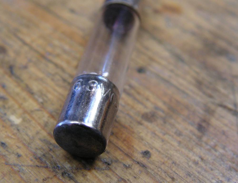
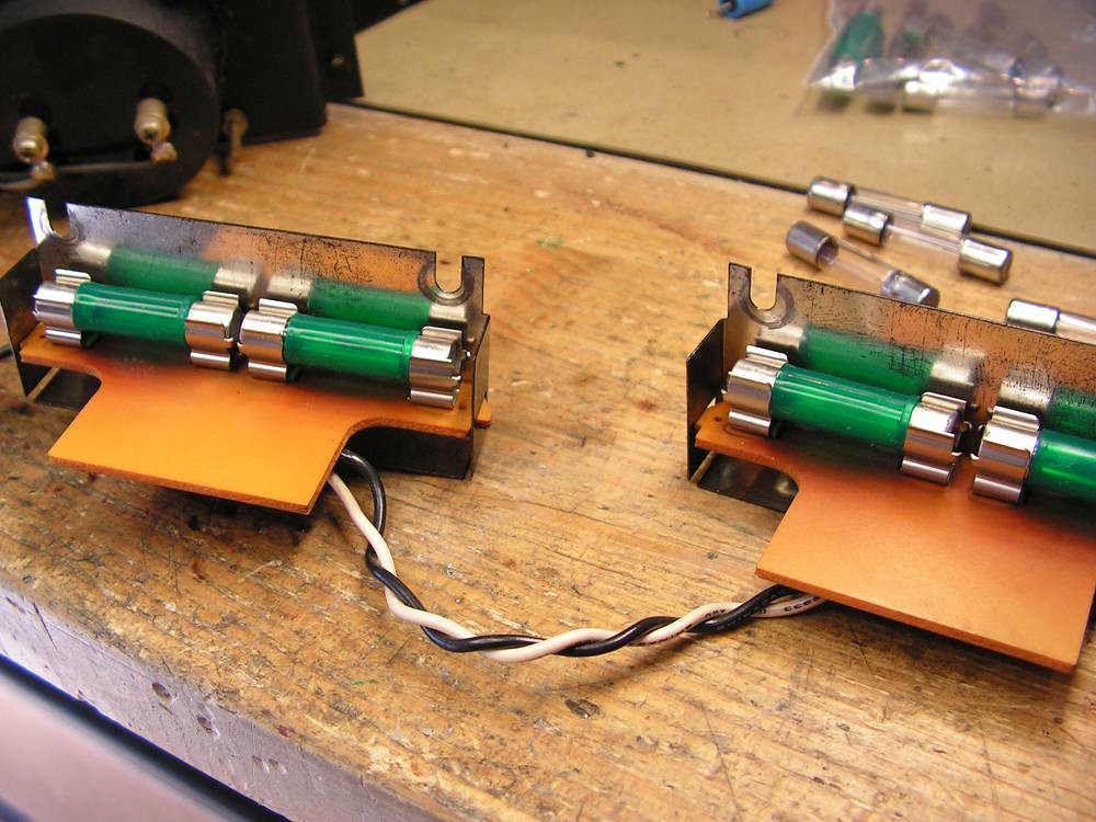
as you can see, the bulb was not like it should be, old bulb was 6.3V, but it should be 7 V
the new correct lamps installed
And now the final step… changing main capacitors…
My choice for that amp (and for BA3000) is Nichicon 22000uF 80V KG Super Through. This is very good capacitor, and with exact the same dimensions as old ones… but they are solder lug (for soldering wires), and old capacitors has contacts by screw and nut… so we have to adopt type of connections…
Old connection
